Elecraft XV Assembly Manual for XV222 User Manual
Page 37
- 34 -
Install two 22
F, 25 VDC electrolytic capacitors near the notch on
the left side of the PCB. Be sure to observe polarity. The longer
positive lead goes in the square solder pad with a
+
silk-screened
next to it.
__C26
__C60
Locate diodes D10 and D11. They are square, red LEDs identical to
the ones you installed on the front panel PCB.
Locate the positions for D10 and D11 on the PCB, near the center on
the right hand side. Note that the square solder pad for D10 is to the left
and the square solder pad for D11 is to the right. The diodes must be
installed turned 180 degrees with respect to each other.
Position diode D10 on the PCB with the long lead through the square
pad on the left and the short lead through the round pad. Position the body
of the LED directly against the PCB within the silk screen outline and
spread the leads under the PCB to hold the diode in place.
Solder one lead on the bottom of the PCB. Check to be sure the LED
is still positioned directly against the PCB. Reheat and adjust the LED as
necessary, then solder and trim both leads.
Position diode D11 on the PCB with the long lead through the square
pad on the right, opposite the orientation of D10. Solder and trim the
leads as you did for D10.
Locate the inductors provided for L15, L16 and L17 in the I.F.
Bandpass filter. They have grey plastic forms visible inside the shields.
Prepare the inductors for installation as follows:
Use the inductor alignment tool to exercise the core in each
inductor. If the alignment tool fits tightly, insert it from the
bottom to avoid pushing the inductor out of the shield. Run the
core up and down through the coil to ensure it runs smoothly
(some inductors are very stiff at first) then position the core near
the top of the coil.
Check the two leads and the two tabs on the case of each
inductor. If they are bent, straighten them carefully using long
nose pliers.
Position each inductor on the PCB so that its tabs and pins protrude
through on the bottom. The inductors can be positioned either way.
Ensure that the shoulders of the tabs are against the top of the PCB, and
then bend the tabs toward each other until they are flat on the PCB to
hold the inductor in place.
__L16
__L15 __L17
Solder the two tabs and the two pins on all three inductors.
Install voltage regulator U2 (78L09) in the space provided near L17.
Be sure to align the body with the silk screen outline on the PCB.
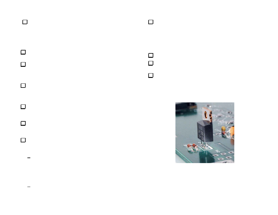
Install transistor Q4 (620) in the space provided near diodes D7 and
D8 as shown in Figure 24. Be sure the leads are inserted until their
shoulders are against the top of the PCB. If the leads are not inserted
far enough, the tab on the top of the transistor may short against the
top cover when the cabinet is assembled. Trim the leads as short as
possible on the bottom of the PCB.
Figure 24. Installing Transistor Q4.