Elecraft XV Assembly Manual for XV222 User Manual
Page 36
- 33 -
Install 4-pole DIP switch SW1 in the space provided in the lower
left quadrant of the PCB. The DIP switch may not have a notch at one end
to line up with the silk-screened outline. Orient the switch so that the ON
positions are on the side with the silk-screened numbers. If you aren’t
sure, use your DMM to check the orientation of the switch assembly so
there is continuity through each switch when the toggle is toward the silk-
screened number on the PCB.
Bend the leads of voltage regulator U4 (UA78M05C) to fit on the
PCB as shown in Figure 21. Bend the leads around the shaft of a small
screwdriver to create smooth rather than sharp bends.
USE SMOOTH BEND
Figure 21. Installing Voltage Regulator U4.
Insert U4’s leads into the holes. Secure it with a zinc or stainless steel
4-40 x 5/16” (8 mm) screw, #4 inside-tooth lock washer and 4-40 nut as
shown. The metal tab on the transistor sits directly against the metal foil
on the circuit PCB.
Solder all three leads to U4 on the bottom side of the PCB and trim
them short.
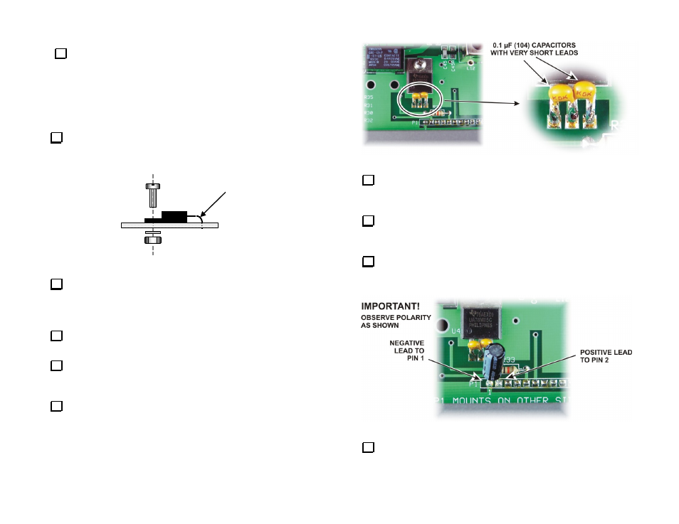
Locate the two 0.1
F (104), 50V, LS 0.1” Monolithic Ceramic
capacitors. These are the capacitors that do not have reference designators
in the parts list.
Install the two 0.1 μF (104) capacitors between U4’s center and outer
pins as shown in Figure 22. Solder the capacitors directly to U4’s pins
with very short leads. Hint: Bend the capacitor leads and hold them with
your pliers while tacking one lead onto U4 with your soldering iron
carrying a small drop of solder. Then solder the other lead, clean up the
first connection if needed, and trim off the excess leads.
Figure 22. Installing the U4 Bypass Capacitors.
Check the resistance between the center pin and each outside pin
using your DMM. It must be greater than 500 ohms to confirm no shorts
between U4’s pins.
Locate the 10
F, (10) 16V electrolytic capacitor. This is the
electrolytic that does not have a reference designator shown on the parts
list.
Solder the 10 μF (10) electrolytic capacitor directly to P1 pins 1
(negative) and 2 as shown below using short leads. Be sure to connect
the negative (-) lead to pin 1 as shown.
Figure 23. Installing the 10 μF Electrolytic Capacitor on P1.
Check the resistance between P1 pins 1 and 2. It must be greater
than 500 ohms to confirm no short between the pins.