Elecraft XV Assembly Manual for XV222 User Manual
Page 39
- 36 -
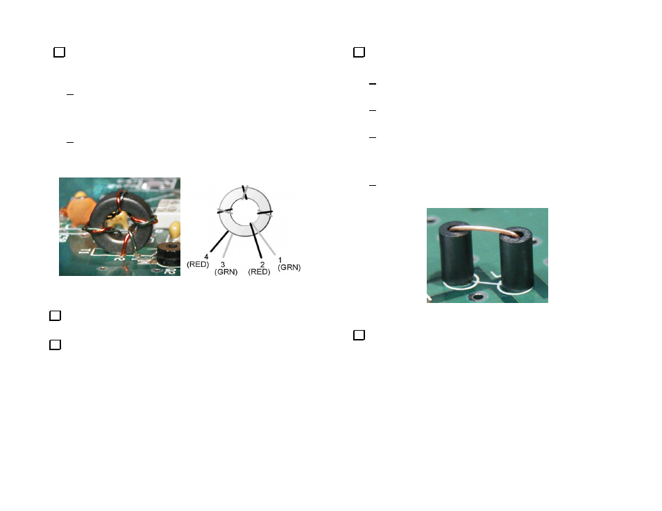
Insert the tinned leads in the holes on the PCB and position the
toroid as shown in Figure 25. Be sure the correct lead goes to each hole.
Use a magnifier to check the following:
Bare, tinned wire should be visible where the wire enters the
hole at the top of the PCB. If necessary remove the toroid and
strip the wire further to ensure the wire going through the hole is
free of enamel and tinned.
Check carefully for shorts between the wires. The toroid core is
not a conductor. Bare wire may touch the core. Be sure that the
tinned wires do not touch each other.
Figure 25. Installing T1.
Solder the wires on the bottom of the PCB and trim the leads as short
as possible.
Locate the solder pads for choke L7 on the left side of the PCB next
to the notch.
Choke L7 consists of a bare wire passing through two ferrite beads
as shown in Figure 26. Prepare and install L7 as follows:
Strip the insulation from 3” (7.5 cm) of the #24 solid insulated
wire provided.
Bend the wire into a U shape to match the spacing of the holes
on the PCB. Place a bead on either side of the bend.
Thread the ends of the wires through the solder pads for L7.
Make sure the beads are sitting vertically on the PCB over each
hole and bend the leads on the bottom of the PCB to hold the
assembly in place.
Solder both leads and trim them as short as possible.
Figure 26. Installing Choke L7.
Install the DPDT power switch at SW2 in the lower right corner of
the PCB. Orient the switch so the pushbutton shaft extends out over the
edge of the PCB. Be sure the two feet on the bottom of the switch are
resting against the PCB before soldering.