Final assembly – Elecraft XV Assembly Manual for XV222 User Manual
Page 53
- 50 -
Final Assembly
In the following steps you’ll finish assembling the transverter.
Remove paint overspray from around the screw holes on the inside
surface of the cabinet back panel where the 2-D fasteners will be attached
(see Figure 44). The 2-D fasteners should make good electrical contact with
the back panel
i
Good electrical contact between all of the chassis parts is essential
for optimum shielding and system noise figure.
Mount antenna connector J1 on the cabinet back panel using four 5/16”
4-40 pan head zinc or stainless steel screws, lock washers, nuts and one
ground lug as shown in Figure 39. Be sure the ground lug is on the lower
screw nearest the end of the back panel and faces upward as shown. The
antenna connector is an S0-239 (UHF) connector on the XV50 transverter,
and a type “N” connector on the XV144 and XV222 transverters.
INSIDE TOOTH
LOCK WASHER
ON EACH SCREW
GROUND LUG ON
BOTTOM SCREW
NEAREST THE END
Figure 39. Mounting the Antenna Connector J1 on the Back Panel.
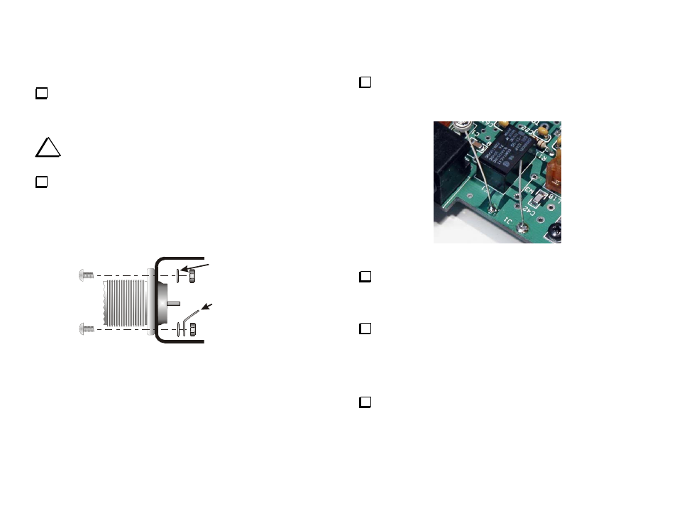
Solder the two clipped leads you saved when you installed D5 (Page
28) to the J1 solder pads on the RF PCB. The J1 pads are near K1 (see
Figure 40).
Figure 40. J1 Solder Pads on RF PCB.
Position the cabinet back panel on the rear of the RF PCB so the 12
VDC, Control, TXn/IF1, RXout/IF2, Key In and Key Out jacks project
through the holes in the cover. Attach the cover to the 2-D fasteners at the
rear of the RF PCB using two 3/16” (4.8 mm) black pan head screws.
Attach the two DB-9 male-female standoffs to the Control
connector. Use a #4 inside tooth lock washer between each standoff and
the rear cover. Note: Do not force the threads. When assembling the
modular chassis, screw holes will sometimes not align perfectly. Loosen
the other screws holding the panel so it can move as needed to align the
holes so all the screws can start easily, then tighten all hardware.
Slip the finish lock washers and nuts over the BNC connectors and
tighten them.