Rf pcb assembly – part iii – Elecraft XV Assembly Manual for XV222 User Manual
Page 50
- 47 -
RF PCB Assembly – Part III
In the following steps you will install the RF power module. The procedure is
the same for all three transverter models.
If you purchased the optional feet and bail for your transverter, install
them on the bottom cover now.
You will use the following small hardware:
14 pan head black screws, 3/16” (4.8 mm) 4-40 thread.
2 pan head black screws, 1/2” (12.7 mm) 4-40 thread.
2 nuts, 4-40 thread.
4 2-D fasteners.
2 flat washers, #4.
2 inside tooth lock washers, #4.
8 split lock washers, #4.
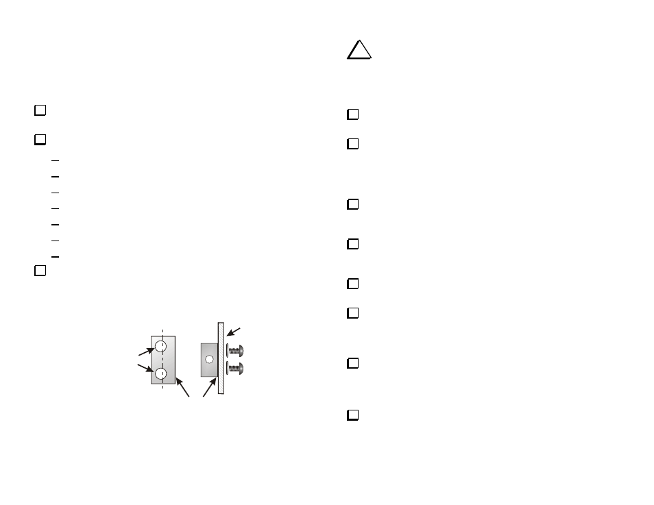
Install four 2-D fasteners on the bottom corners of the RF PCB. Line up
the offset holes of each 2-D fastener so the side of the connector is flush with
the edge of the PCB (see Figure 34). Secure each connector to the PCB with
two black 3/16” (4.8 mm) pan head screws and split lock washers.
HOLES OFFSET
FROM CENTER
TOP OF
BOARD
LINES UP FLUSH
WITH EDGE OF
BOARD
C
L
Figure 34. 2-D Fasteners.
i
In the following steps you will install the hardware that
attaches the RF power module to the bottom cover. Follow the steps
carefully to ensure the module makes good thermal contact with the
bottom cover and the leads line up properly with the RF PCB. The
completed hardware assembly is shown in Figure 38 .
Locate the bottom cover. The bottom cover has two sets of cooling
holes.
On the inside surface of the bottom cover, locate the four holes that
match the holes in the heat spreader. They are between the two sets of
cooling holes. Test-fit the larger of the two thermal conduction pads so
that the holes in the pad line up with the holes in the cover. Orient the pad
so it does not hang over the edge of the bottom cover.
Lift the thermal conduction pad and clean the surface of the bottom
cover under the pad using sandpaper, a sharp knife or other tool. The pad
must rest against clean, bare metal.
Clean the paint off of the inside surface of the bottom cover around
the screw holes in the four corners where the 2-D fasteners will attach it
to the RF PCB (See Figure 37).
Inspect the edges of the heat spreader and remove any burrs with the
edge of a flat-blade screwdriver, knife or small file.
Replace the larger of the two thermal conduction pads over the clean
metal area on the inside of the bottom cover so that the holes line in the
pad line up with the holes in the cover. Be sure the pad does not hang
over the edge of the bottom cover.
Place the heat spreader on the thermal conduction pad on so the
screw holes line up. Put a 1/2” (12.7 mm) pan head screw through each
unthreaded hole with the head on the bottom cover. Place a nut on each
screw and finger tighten.
Insert two black 3/16” (4.8 mm) pan head screws through the bottom
cover into the threaded holes in the head spreader. Tighten the screws.