Elecraft XV Assembly Manual for XV222 User Manual
Page 31
- 28 -
Install the following 3-watt resistors above R21 near the center of
the PCB. Space each resistor about 1/16” (1.5 mm) above the PCB just
like you did for the 1-watt resistors.
__R20, 160 ohm (160)
__R26, 160 ohm (160)
__R27, 160 ohm (160)
Install the 1/4-watt 1% tolerance resistors listed below in the lower
left quadrant of the PCB. Place these and all of the rest of the resistors
directly against the PCB.
R35, 5.11k (grn-brn-brn-brn)
R31, 15.0k (brn-grn-blk-red)
R30, 7.5k (vio-grn-blk-brn)
R32, 3.92k (or-wht-red-brn)
Install the 1/4 watt resistors listed below. Start with R1, which is in
the upper left quadrant just above the cutout in PCB. The locations follow
the perimeter of the PCB going clockwise.
__R1, 10k (brn-blk-org)
__R11, 1k (brn-blk-red)
__R14, 4.7 ohm (yel-vio-gld)
__R23, 100k (brn-blk-yel)
Install the 1/4 watt resistors listed below. Start with R4, which is in
the lower right quadrant above Z4. The locations follow the perimeter of
the PCB going clockwise.
__R4, 5.6k (grn-blu-red)
__R25, 56 ohm (grn-blu-blk)
__R5, 5.6K (grn-blu-red)
__R7, 10k (brn-blk-org)
__R34 (on the right edge of the PCB), 100k (brn-blk-yel)
__R9, 10k (brn-blk-org)
__R33, 10k (brn-blk-org)
Install the following 1/4 watt resistors next to Q6 at the center of the
PCB:
R18, 620 ohm (blu-red-brn)
R40, 22k (red-red-org)
Locate the silk-screened space for D5 on the PCB near R23 in the
upper right quadrant of the PCB.
i
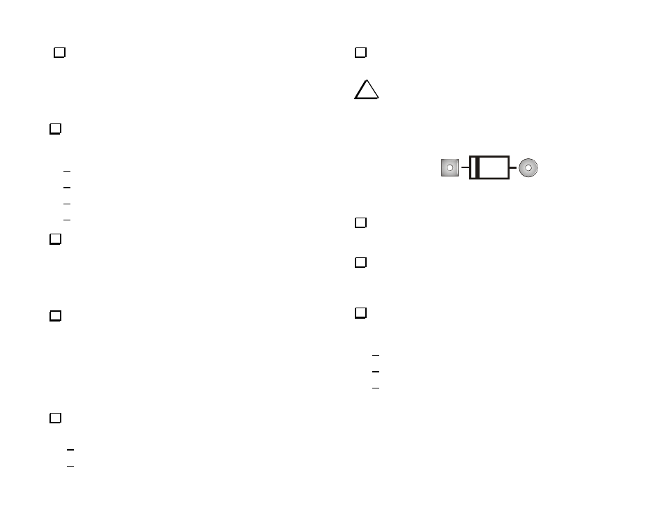
Diodes must be oriented correctly. A black band around the
diode indicates the cathode end. Install each diode so the cathode end
goes to the square solder pad and the band is oriented to match the silk-
screened outline (see Figure 16 below). If a diode has more than one
band, the widest band indicates the cathode end.
Figure 16. PCB Diode Orientation Guides. The cathode always goes
to the square solder pad on the PCB.
Install D5 (SB530) so it is against the PCB and the banded end of
the diode is aligned with the banded end of the PCB outline. Save the
excess leads when you clip them.
Put the clipped leads from D5 in a safe place. Keep them separate
from the other clipped leads you are saving for test points and jumpers.
You will use the leads from D5 when you install antenna connector J1
later.
Sort the small glass diodes by type. If necessary use a strong
magnifier to read the tiny numbers printed on the glass body. Tape each
group to a piece of paper marked by the type number.
1 ea. 1N5235
2 ea. 1N5711
10 ea. 1N4148