Elecraft XV Assembly Manual for XV222 User Manual
Page 30
- 27 -
Adjust the L-bracket positions so the front panel PCB is aligned
with the RF PCB. If the gap between the front panel PCB and the RF PCB
is wider at one end than the other, you probably have one of the brackets
installed backward. Be certain the shorter legs are attached to the RF
PCB.
P1
Top of RF board
J1
Figure 14. Installing J1 and P1.
Tighten all four L-bracket screws.
Solder all pins of J1 and P1.
Remove the two screws holding the front panel PCB to the brackets.
Unplug the front panel PCB and set it aside in a safe place.
Remove the brackets and screws from the RF PCB and set them
aside.
Sort the fixed resistors by wattage and value as follows:
Divide the resistors by wattage: 3-watt (physically largest), 1-watt
and 1/4 watt (smallest).
Among the 1/4 watt resistors, separate the four 1% tolerance
resistors. These resistors have five color bands: four color bands
show the value plus a brown color band at one end that is wider
than the others. The wide band indicates that it is a 1% tolerance
resistor.
Sort the remaining 1/4 watt resistors by value. If the color bands
are difficult to read, use a DMM (digital multimeter) to verify
their values. Tape them to a piece of paper with the values
labeled.
Place the PCB with the silk-screened side up and the cutout to your
left. The lettering in the center of the PCB will read right side up. All of
the remaining parts will be installed on the top, silk-screened side of the
PCB.
i
Save the longer clipped leads from the following resistors.
You will use several of them to make jumpers and test points later.
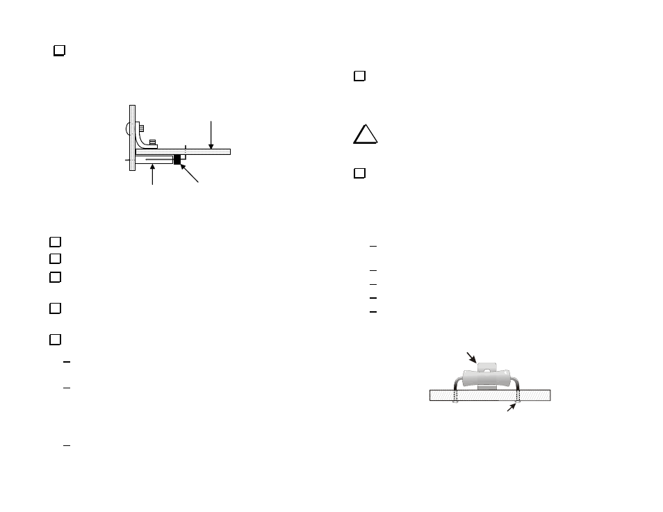
Install the 1-watt resistors listed below. Space each resistor about
1/16” (1.5 mm) above the PCB by placing the long end of one of the
right-angle brackets between the resistor and PCB until the resistor is
soldered in place (See Figure 15). The objective is to leave space for air
to flow around the resistor. The resistors that should be spaced above the
PCB are shown by a double silk screen outline.
R12, 180 ohm (brn-gry-brn), near U1 in the upper left quadrant
of the PCB.
R16, 120 ohm (brn-red-brn) next to R12.
R21, 820 ohms (821), 1 watt next to Q6.
R19, 180 ohm (brn-gry-brn), near U5 at the center of the PCB.
R8, 120 ohm (brn-red-brn) near Z1 in the lower right quadrant
of the PCB.
PLACE RIGHT-ANGLE BRACKET
UNDER EACH RESISTOR UNTIL
IT IS SOLDERED IN PLACE
SOLDER & TRIM LEADS
Figure 15. Spacing the 1-watt and 3-watt Resistors above the PCB.