Rf pcb assembly – part i – Elecraft XV Assembly Manual for XV222 User Manual
Page 29
- 26 -
RF PCB Assembly – Part I
RF circuit assembly is divided into three parts:
Part 1: DC, control circuits and RF components common to all of the
transverters.
Part 2: Additional RF components unique to the specific band transverter
you are building.
Part 3: Installation of the RF power module.
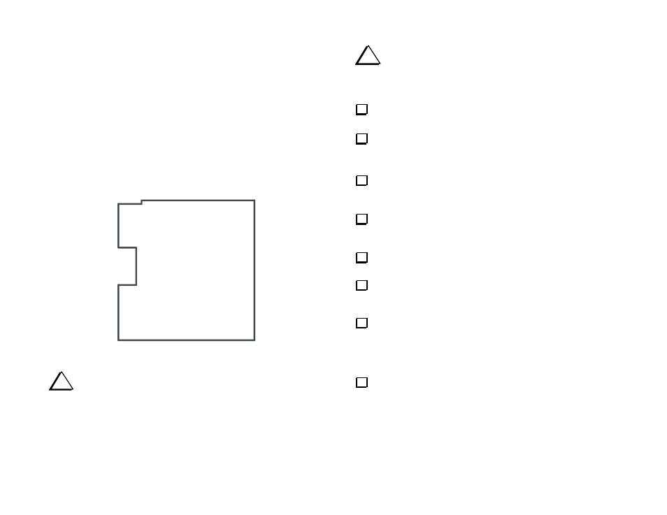
To help you locate the component positions on the large RF PCB, the
following steps refer to the five general areas of the PCB shown in Figure
13 . Orient the PCB as shown with the component side up.
TOP LEFT
QUADRANT
TOP RIGHT
QUADRANT
LOWER LEFT
QUADRANT
LOWER RIGHT
QUADRANT
CENTER
Figure 13. RF PCB Orientation.
i
Take ESD precautions (see page 3) when handling
the RF
PCB. Some surface-mounted components are used in the RF circuits
for optimal transverter performance. The PCB is supplied with these
components pre-mounted. Take care not to damage them.
i
Do NOT remove the temporary wire jumper across the solder
pads for L1 until instructed to do so. This jumper protects U1 from
static damage until the circuits are completed.
Locate the two small L-brackets. Identify the shorter side of the
"L", which will be attached to the RF PCB.
On the RF PCB, locate the hole at either end of the silk-screened
lettering:
P1 MOUNTS ON OTHER SIDE OF BOARD
. These are the holes
where “L” brackets will be installed.
Secure the shorter leg of an L-bracket loosely to the RF PCB in
each hole using a 4-40 x 3/16” (4.8 mm) black screw. A lock washer is
not required at this time.
Locate the 12-pin female connector (J1) and the 12-pin male
connector (P1). Normally J1 is included with the front panel PCB parts
and P1 is with the RF PCB parts.
Slide the 12-pin female connector (J1) onto the pins of the 12-pin
male connector (P1). There should be no gap between them.
Insert P1's right-angle pins into the holes on the bottom of the RF
PCB near the letters:
P1 MOUNTS ON THIS SIDE OF BOARD
. Do not
solder yet.
Position the front panel PCB as shown in Figure 14. The pins of J1
should be inserted into the holes in the front panel PCB, and the two L-
brackets should be aligned with their outlines on the back of the front
panel PCB. The edge of the RF PCB fits between the socket for U1 and
Q2, Q3, Q4 and Z1 on the front panel PCB.
Secure the L-brackets loosely to the front panel using two 4-40 x
3/16" (4.8 mm) screws (black). It is not necessary to use lock washers at
this time.