Elecraft XV Assembly Manual for XV222 User Manual
Page 40
- 37 -
Locate the two RCA Jacks, J4 and J5. Use your flush cutters to trim
off the two small plastic feet on each jack (see Figure 27). Be sure they
are cut flush so the jacks will sit squarely against the PCB when installed
in the next step.
TRIM OFF THE TWO PLASTIC
FEET FLUSH WITH THE
BOTTOM OF THE JACK.
Figure 27. Preparing the RCA Jacks for Installation.
Install two RCA jacks at the top of the PCB. Solder one pin first
then check to be sure the jack is sitting flat against the PCB. If necessary,
reheat the solder while pressing down on the jack. Solder the second pin
then trim the leads.
__J5 __J4
i
J8, installed in the next step, is not required if you are
building your transverter to use a common transmit and receive
antenna. J8 is needed only if you plan to use separate (split-path)
transmit and receive antennas. It won’t hurt to install it in any case.
Install three BNC jacks at the top of the PCB. Line up the two
supports and the two small conductor pins with the holes and gently press
the connectors down until the four plastic pins on the jack rest directly
against the PCB. Solder one of the large pins, then check the position. If
necessary, reheat the solder while pressing down on the jack. After
soldering all four pins, trim off the excess length of the small pins.
__J8 __J2
__J3
Install the DB-9 connector at J6 and solder the pins including the two
larger mounting pins.
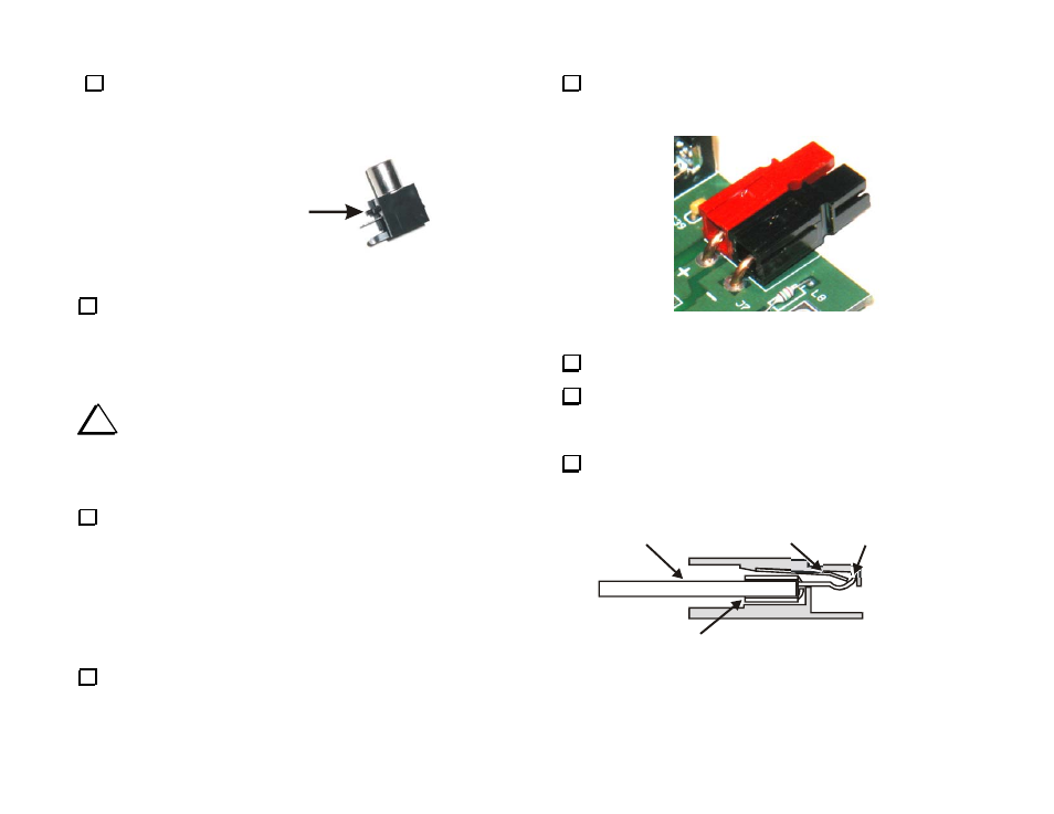
The Anderson power connector is held in place by two heavy copper
wires soldered to the PCB (See Figure 28). Prepare and install the
connector as described in the following steps.
Figure 28. Installing J7.
Cut the length of #14 copper wire provided in half.
Solder each length of the #14 copper wire into the crimp terminal
end of an Powerpole® contact. Solder, do not rely on a crimp
connection. Take care to keep solder off of the terminal.
Orient each contact as shown in Figure 29 and slide it into a
housing until it “clicks” in place. Tug on the wire to be sure it is locked
in place. If the contact comes out, you probably have it in upside down.
SPRING
#14 WIRE
SOLDERED
TERMINAL LOCKS
OVER END OF SPRING
Figure 29. Inserting Contact into Anderson Connector Housing.