Elecraft XV Assembly Manual for XV222 User Manual
Page 33
- 30 -
Solder Q2 in place as follows:
_ Wet your soldering iron with a small amount of solder and touch
it to one lead of Q2 tack-solder it in place.
_ Check alignment of the other two leads to be sure they are over
the solder pads. If necessary reheat the tack-soldered lead and
adjust the position of the transistor.
_ Solder all three leads properly, soldering the tack-soldered lead
last. Keep your soldering time as short as possible to avoid over-
heating the transistor. Do not hold the iron on the leads more
than two seconds.
i
Check each capacitor's labeling carefully to ensure the values
agree with the numbers shown in parenthesis.
Install the monolithic capacitors listed below near U3 and Q6 at the
center of the PCB.
__C68, .047
F(473) __C67, .01 F (103) __C64, .01F (103)
__C65, .047
F (473) __C10, .01 F(103) __C9,
.01
F (103)
Install the monolithic capacitors listed below. With the PCB oriented
with the cutout to the left, start with C62 near the lower left and work
around the PCB clockwise to the upper right quadrant.
__C62, .01
F (103) __C40, .01 F (103) __C7, .001 F (102)
__C8, .01
F (103) __C3, .001 F (102) __C63, .01F (103)
__C6, .01
F (103) __C22, .01 F (103) __C61, .01 F (103)
__C2, 100 pF (101)
__C23, .01 F (103) __C38, .01 F (103)
__C27, .01
F (103) __C29, .047 F(473) __C37, .01 F (103)
__C35, 10 pF (100)
__C36, F .01 (103) __C34, .01 F (103)
__C39, .001
F (102)
Install the monolithic capacitors listed below. Start with C71 on the
edge of the PCB in the lower right quadrant and work from right to left
across the lower part of the PCB.
__C71,.01
F (103) __C15, .001 F(102) __C16, .01 F (103)
__C20, .01
F (103) __C30, 0.22 F(224) __C17, .001 F(102)
__C19, .01
F (103) __C57, 100 pF (101)
Install disc ceramic capacitor C18 (2.2) next to C17 in the lower
right quadrant of the PCB.
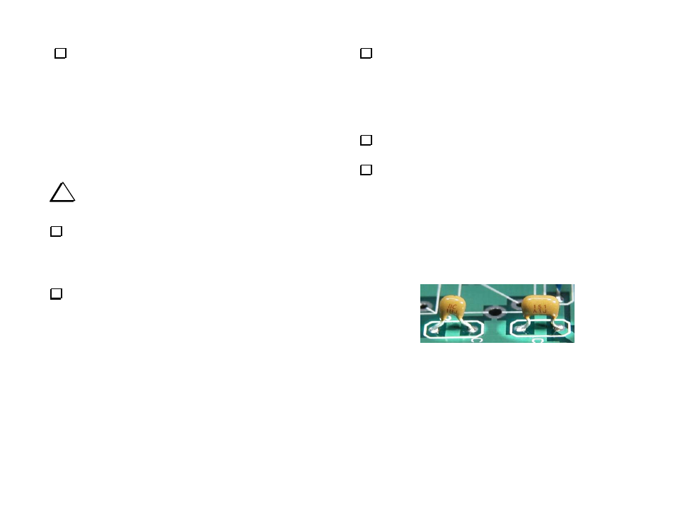
Install the capacitors listed below in the area near the center of the
PCB marked
28 MHZ IF BANDPASS FILTER
. The lead spacing of these
capacitors may be narrower than the hole spacing on the PCB. If
necessary, form the leads to avoid stress on the capacitor when they are
inserted in the PCB. Do not force the capacitors down against the
PCB. The capacitors may sit about 1/16” (1.5 mm) above the PCB as
shown in Figure 18 .
__C55, 270 (271)
__C54, 150 (151)
__C53, 18 (180) or (18)
__C52, 150 (151)
__C56, 270 (271)
The capacitors shown are typical.
Other styles may be supplied.
Figure 18. Installing I.F. Filter Capacitors.