Elecraft XV Assembly Manual for XV222 User Manual
Page 35
- 32 -
Install resettable fuse F1 in the space provided next to relay K9 in
the upper right quadrant. F1 may be oriented either way. Solder and trim
the leads.
Check the pins on the large relay (KLT1C12DC12). If any pins are
bent, straighten them carefully using long-nose pliers.
Install the main power relay K3 (KLT1C12DC12) next to F1 and
solder two diagonally opposite corner pins. Check the relay to ensure it is
flush against the circuit PCB. If necessary, reheat the solder while
pressing down on the relay.
Solder all five pins on relay K3. Do not trim the relay pins.
Trimming the pins can cause mechanical stress which may reduce the life
of the relay.
Install a 3-terminal header at JP1 adjacent to relay K8. Put a shorting
block over two pins of the header to provide a surface where you can
place your finger to keep it straight and against the PCB. While holding
the assembly, touch one of the pins on the bottom of the PCB with a
soldering iron to tack-solder it in place. Check to ensure that the header is
sitting vertically on the PCB (see Figure 10 on page 23). Reheat and
adjust as necessary, then solder all three pins. Do not hold the solder
iron on the pins more than 1 or 2 seconds. Excessive heat will melt the
plastic part of the header.
Remove the shorting block from JP1.
Install the following 3-terminal headers:
JP2 next to relay K8.
JP3 next to relay K8.
JP4 near resistor R21.
JP5 near relay K6.
JP6 near relay K6.
Install JP9 next to K4 and K5. JP9 requires one 2-terminal header
and one 3-terminal header.
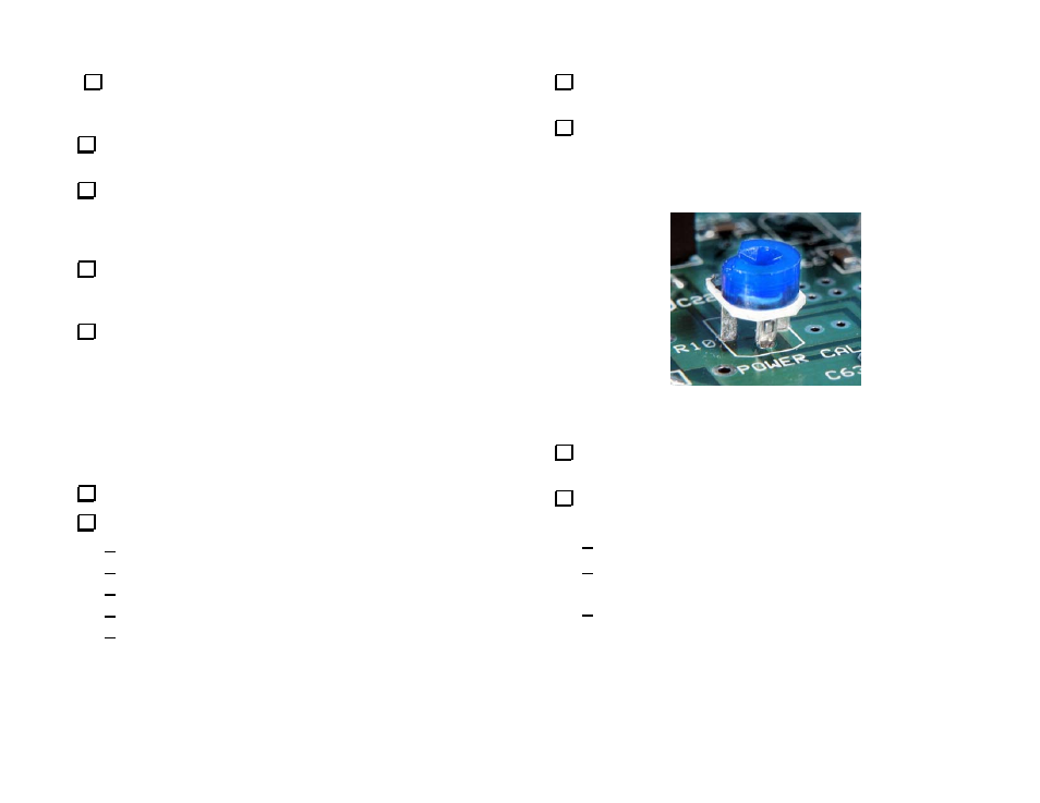
Install the 100 k-ohm (104) potentiometer R10 (Power Cal) in the
upper left quadrant of the PCB. The center lead goes toward the beveled
end of the silk screen outline (see Figure 20). The shoulders on the leads
should touch the top of the PCB. This pot also may be marked 15K. That
is a manufacturer’s mark, not the value.
Figure 20. Installing PC Board Pots. Orient the center pin toward
the beveled end of the silk-screened outline.
Spread the leads on R10, if necessary, to hold it in place, then solder
and trim the leads.
Install the two 100 ohm PC board potentiometers just as you did
R10:
R13 (101) in the upper left quadrant of the PCB near D3.
R22 (101) below the three 160-ohm 3-watt resistors near the
center of the PCB.
Verify that all three terminals on each pot are soldered.