Front panel pcb assembly – Elecraft XV Assembly Manual for XV222 User Manual
Page 24
- 21 -
Front Panel PCB Assembly
Place the front panel PCB on top of the heat spreader with the silk-
screened side down as shown in Figure 4. Temporarily attach the PCB to
the heat spreader with a single 3/16” (4.8 mm) pan-head screw.
FRONT-PANEL PCB
SILK-SCREENED SIDE DOWN
Figure 4. Preparing Front Panel PCB to Install Light Bar.
Prepare the leads of the yellow light bar for mounting on the PCB by
bending them as shown in Figure 5. Press the leads against a smooth, hard
surface and roll the roll the light bar until they are at about a 45 degree
angle to the side of the light bar.
1
2
3
.
Figure 5. Preparing Light Bar Leads.
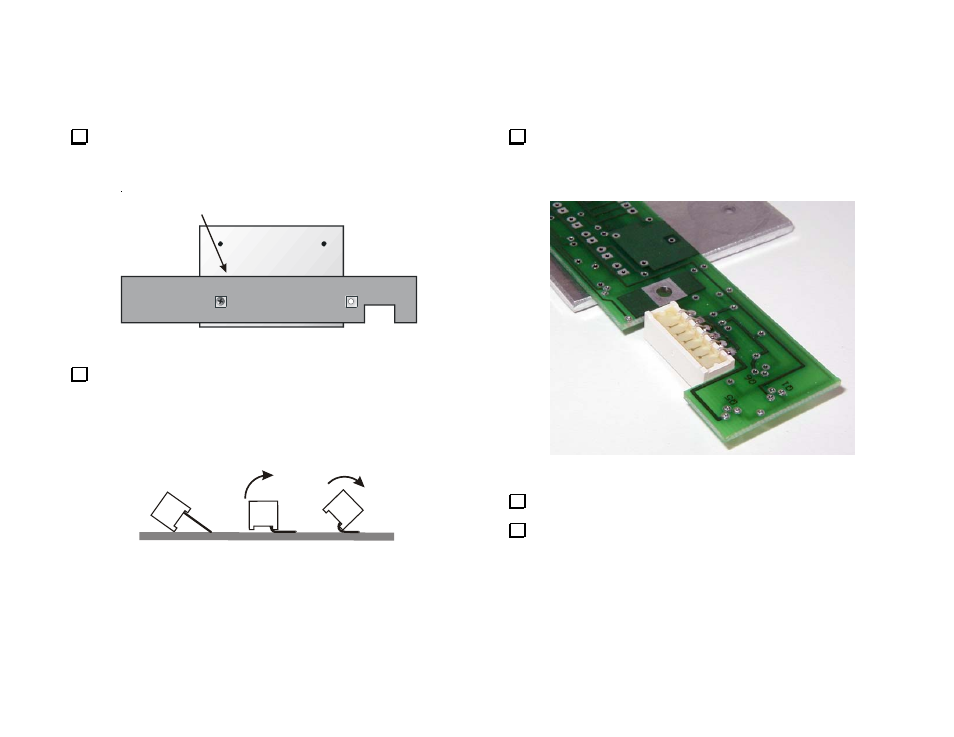
Position the light bar in the cutout of the PCB as shown in Figure 6.
Adjust the leads as necessary so they line up with the six solder pads at
the edge of the cutout. The leads will not pass through the solder pads.
The tips of the leads will rest just inside the top of each solder pad.
Figure 6. Installing Light Bar.
Solder the six terminals to the PCB pads.
Remove the front panel PCB from the heat spreader.