Elecraft XV Assembly Manual for XV222 User Manual
Page 55
- 52 -
i
When U1 is pressed into its socket, you must be careful to avoid
jamming its pins. Make sure all the pins are lined up with the associated holes
before pressing down on the IC. Watch the pins on both rows as you press down
to be sure each pin goes straight down into its socket hole and does not bend in
under the IC or outward alongside the socket. Realign each pin individually
with its socket hole, if necessary.
Insert processor U1 in its socket with pin 1 or the notched end lined up
with the notched end of the socket (the end farthest from the edge of the front
panel PCB). Be careful while pressing U6 into its socket not to bend or
damage the power indicator LEDs on the front side of the PCB.
Insert plug P1 on the front panel PCB into J1 on the bottom of the RF
PCB, and then secure the front panel PCB to the two right angle brackets
with 3/16” (4.8 mm) screws and split lock washers.
Place the cabinet front panel face up on your work surface and attach the
label with two 2-56 screws. Orient the label with the lighter side upward so
that the band identification reads correctly when viewed from the front.
Fit the front panel over the power pushbutton and power LEDs. Attach
the front panel to the 2-D fasteners on the bottom of the RF PCB with two
3/16” (4.8 mm) screws.
Press the key cap onto the On/Off switch shaft until it clicks in place.
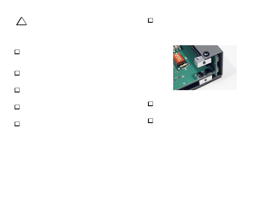
Attach a 2-D fastener to the each screw hole at the top corners of the
front and rear chassis end panels with 3/16” (4.8 mm) screws. Be sure
the widest side of each 2-D fastener is facing toward the end of the panel
so the edge lines up flush with the edge of the panel as shown in Figure
44.
Figure 44. Attaching 2-D Fasteners to Cabinet End Covers.
Inspect the inside surface of the side covers and remove any paint
overspray around the screw holes to ensure good electrical contact with
the 2D fasteners.
Attach the side panels using four 3/16” (4.8 mm) screws in each
panel. You many need to loosen the other screws holding the end covers
temporarily to line up the screw holes properly.