Elecraft XV Assembly Manual for XV222 User Manual
Page 47
- 44 -
XV222 – 222 MHz Transverter
Perform the following steps on the RF PCB only if you are building the
XV222 transverter.
Install the resistors listed below.
R24, 56 ohm (grn-blu-blk), 2 watt, in the lower left quadrant near
U6. Space this resistor about 1/16” (1.5 mm) above the PCB like
you did the 1-watt and 3-watt resistors earlier (See Figure 15).
R28, 1k (brn-blk-red), 1/4 watt, near L7 on the middle left. Place this
resistor directly against the PCB.
R29, 56 ohm (grn-blu-blk), 1/4 watt, in center of PCB.
R6, 220 ohm (red-red-brn), 1/4 watt, above Q2 and U2.
Install Z4, a 56 ohm (grn-blu-blk) 1/4 watt resistor in the lower right
quadrant of the PCB.
Install a jumper wire across the solder pads for L3 to the left of toroidal
transformer T1 in the lower right quadrant.
Install two .1
H (brn-blk-silver) molded inductors:
L2 near U1 in the upper left quadrant of the PCB.
Z3 near U6 in the lower left quadrant of the PCB.
Install the following capacitors near the circular outline for OV1 in the
lower right quadrant:
__C13, .047
F (473) __C12, 15 pF (15)
__C14, 22 pF (220)
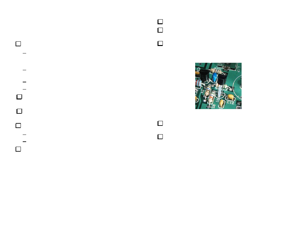
Cut the Teflon tubing to a length of 3/8” (8mm).
Slide the 3/8” (8mm) length of Teflon tubing over the center lead of
transistor Q1 (NTE108).
Install transistor Q1 (NTE108) near U2 so that the Teflon tubing acts
as a spacer to hold the transistor above the PCB. One end of the tubing
should contact the bottom of Q1’s case and the other end should rest
against the top of the circuit PCB (see Figure 33).
Figure 33. Installing Q1 with Teflon Spacer.
Install voltage regulator U3 (78L05) to the left of relay K6 at the
center of the PCB.
Install crystal Y1 where indicated by the silk-screened outline inside
circle OV1. The crystal may be oriented either way. Be sure the crystal
case is sitting directly on the PCB. Do not hold your soldering iron on
the leads more than 2 or 3 seconds maximum. Excessive heat may
damage the crystal.