Elecraft XV Assembly Manual for XV222 User Manual
Page 32
- 29 -
Install zener diode D3 (1N5235) in the upper left quadrant of the
PCB near R12. Position it against the PCB with the banded end aligned
with the banded end of the PCB outline.
Install the two 1N5711 diodes in the lower right quadrant of the PCB.
Place each diode against the PCB with the cathode band oriented as you
did in the previous steps.
__D7
__D8
Install the 1N4148 diodes listed below. Start with D1, which is near
resistor R1 in the upper left quadrant of the PCB and work clockwise
around the PCB.
__D1
__D12 __D6 __D9
__D13
__D14
__D15
__D16 (In lower right quadrant),
__D2
__D4
i
In the following steps you will install molded inductors. These
inductors look much like 1-watt resistors but the color codes read
differently. The color codes on the inductors read from the center to
the end instead of from the end towards the center like resistors.
Install molded inductor L8, 15
H (brn-grn-blk) in the upper right
quadrant of the PCB.
Install molded inductor L9, 0.47
H (yel-vio-silver) about half way
up the PCB about 2 inches (5 cm) from the right-hand edge.
Install transistor Q6 (PN2222) next to R21 near the center of the
PCB. Orient the transistor as shown by the silk-screened outline on the
PCB.
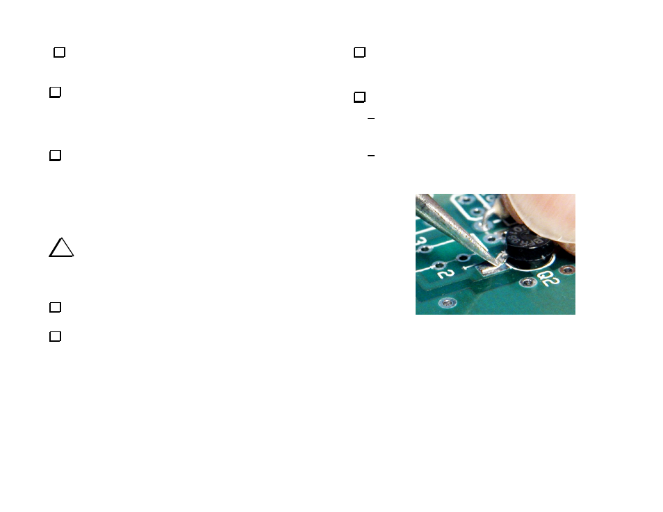
Prepare transistor Q2 (BFR96) for installation as follows:
Place the transistor over the outline on the PCB with the lettered
side up and note the lead lengths required to match the three
solder pad areas on the PCB. Trim the leads to match these pads.
Gently bend the leads down so they make solid contact with the
PCB starting close to the body of the transistor. This is easily
done by pressing down on the lead with a small flat-blade
screwdriver (see Figure 17).
Figure 17. Installing Transistor Q2. Use gentle pressure with a small
screwdriver blade to form the leads.