Elecraft XV Assembly Manual for XV222 User Manual
Page 28
- 25 -
Sort all of the resistors by value. If the color bands are difficult to
read, use a DMM (digital multimeter) to verify their values. Tape them to
a piece of paper with the values labeled.
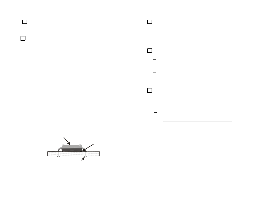
Install the resistors below on the front (silk-screened) side of the
PCB. Align each resistor to rest against the PCB inside the silk-screened
outline (See Figure 12). Start with R1 near the light bar end of the PCB.
__R1, 220 ohm (red-red-brn)
__R16, 120 ohm (brn-red-brn)
__R22, 120 ohm (brn-red-brn)
__R21, 120 ohm (brn-red-brn)
__R24, 2.2k (red-red-red)
__R2, 470 ohm (yel-vio-brn)
__R25, 270k (red-vio-yel)
__R23, 120 ohm (brn-red-brn)
__R14, 120 ohm (brn-red-brn)
__R15, 120 ohm (brn-red-brn)
__R13, 120 ohm (brn-red-brn)
__R5, 1 meg (brn-blk-grn)
__R3, 10k (brn-blk-org)
__R18, 2.2k (red-red-red)
__R20, 2.2k (red-red-red)
__R4, 100k (brn-blk-yel)
__R17, 100k (brn-blk-yel)
__R19, 2.2k (red-red-red)
__R12, 120 ohm (brn-red-brn)
__R11, 120 ohm (brn-red-brn)
__R10, 120 ohm (brn-red-brn)
__R9, 120 ohm (brn-red-brn)
__R8, 120 ohm (brn-red-brn)
__R7, 120 ohm (brn-red-brn)
__R6, 120 ohm (brn-red-brn)
BODY OF PART
AGAINST THE BOARD
ENSURE MARKINGS AGREE WITH
INSTRUCTIONS IN TEXT
SOLDER & TRIM LEADS
Figure 12. Installing Resistors.
Install the two capacitors listed below on the front (silk-screened)
side of the PCB, near the outline of the 28-pin IC socket. Check each
capacitor's labeling carefully (shown in parentheses).
__C2, .01
F (103)
__C3, .01
F (103)
Inspect the PCB carefully for the following:
All connections soldered.
No solder bridges between pads (use a magnifier as needed).
All leads clipped to no more than 1/16” (2 mm) long.
Uninstalled Components
Verify that all component locations on the front panel PCB are
filled, except the following:
U1 (controller 16F872) should not be installed in its socket yet.
J1 at the bottom center of the PCB. This will be installed in the
next section.
You’ve finished the front panel PCB assembly procedure. Go to the RF
PCB Assembly – Part I on the next page to continue.