Elecraft XV Assembly Manual for XV222 User Manual
Page 52
- 49 -
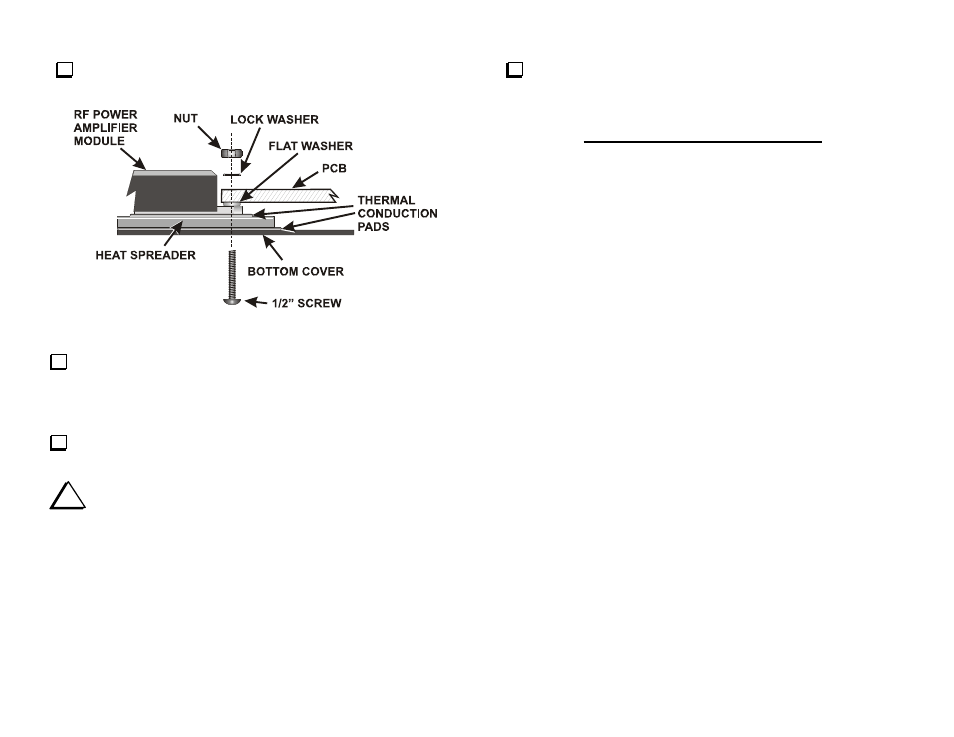
Inspect the RF Power module to be sure you have the module and
hardware installed exactly as shown in Figure 38.
Figure 38. RF Amplifier Module Mounting Hardware.
Adjust the position of the RF Power module to provide the best
alignment of the leads with the solder pads on the PCB. If necessary, loosen
the nuts slightly to allow the module to move within the limits of its screw
holes.
Hold the RF Power module in place and tighten both screws and nuts to
secure it.
i
Be sure the four screws holding the RF Power module and heat
spreader are tightened securely to ensure good heat transfer. Otherwise
the RF Power module may overheat and fail.
Solder the RF power module leads to their corresponding pads on the
PCB. Before soldering, trim the leads as needed so they do not extend
beyond the solder pads.
This finishes Part III of the RF PCB Assembly. Proceed directly to
Final Assembly.