Nikon LS-10 Installation Guide for Windows User Manual
Page 51
Attention! The text in this document has been recognized automatically. To view the original document, you can use the "Original mode".
Mounting the IS-10
Chapter 4
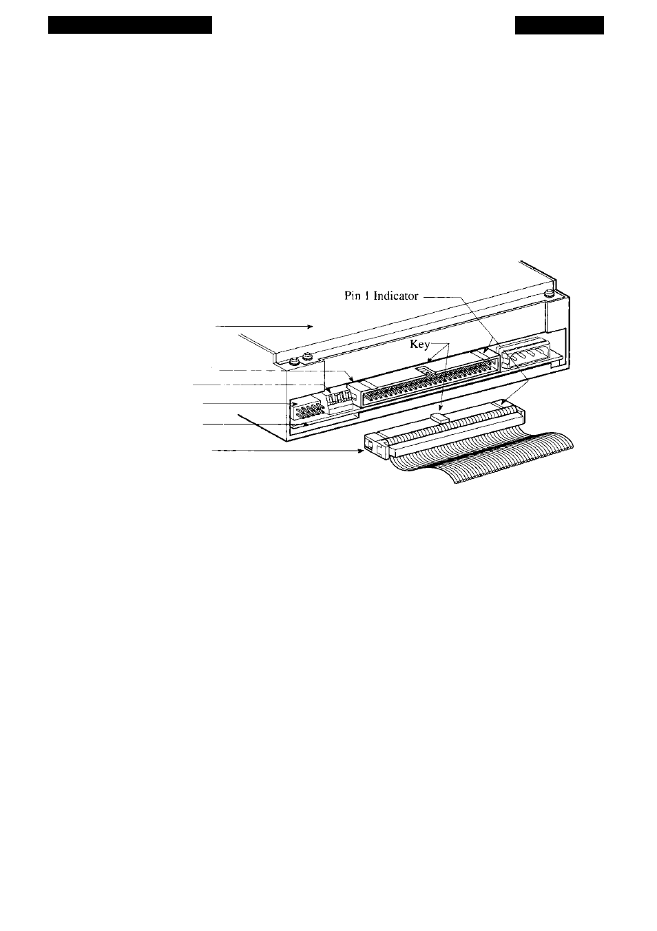
insertion). The cable’s connector should be oriented so that its key and ribbed side face
upwards and is parallel with the connector on the scanner, as shown in Figure 4.2.
Firmly insert the connector. It should seat with very little force. If there is strong
resistance, do not apply excess force. Remove the connector and confirm that you are
inserting it in the correct orientation.
Never force the SCSI cable connector into the scanner’s SCSI connector. This can
result in damage to the connector.
(a) Coolscan Scanner
SCSI Connector
DIP Switch
External Connector
Circuit Card
(b) SCSI Flat Cable
Figure 4.2
Connecting the SCSI flat cable to the Coolscan SCSI connector, (a) Rear of
Coolscan Internal model, (b) SCSI flat cable showing keying and ribbed side facing upwards.
Step 3. Connect the opposite end of the 50-pin SCSI flat ribbon cable to the 50-pin
SCSI connector on the SCSI controller card.
Follow the guidelines in Step 2 to insert the opposite end of the SCSI cable to the
SCSI connector on the SCSI controller card.
Step 4. Connect power to Coolscan.
Shown in Figure 4.3 are different 4-pin power connectors, which are used to con
nect 12V DC and 5V DC power to Coolscan. An optional 4-pin Y-Adapter is provided
for cases where no 4-pin power connector is available in the computer to connect to
Coolscan.
Feed the computer’s 4-pin power connector through the drive bay from the inside
as far as it will extend into the drive bay.
Page 44
Nikon
Coolscan Installation Guide for Windows