The rear panel - ls-10, The rear panel — ls-10 – Nikon LS-10 Installation Guide for Windows User Manual
Page 14
Attention! The text in this document has been recognized automatically. To view the original document, you can use the "Original mode".
Chapter 2
Setting Up Coolscan
SCSI Termination
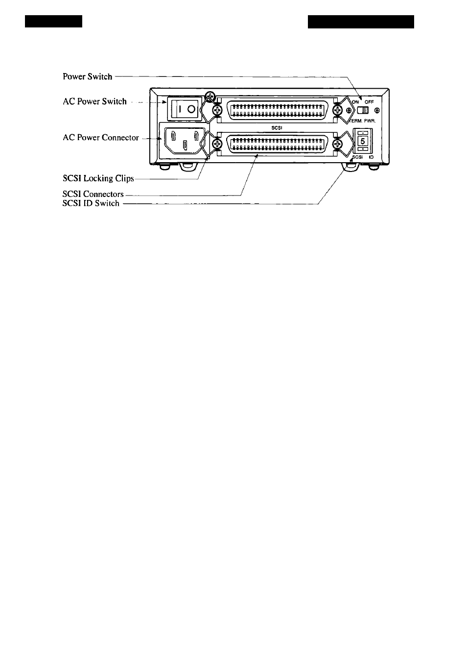
Figure 2.2
Coolscan’s rear panel - LS-IOE.
The AC power switch and AC power connector should be familiar to you. The AC
power switch is used to turn power to the scanner on and off. The AC power connector
receives the female end of the AC power cord.
The three SCSI-related items on the rear panel will be explained in detail in the
next chapter, “The SCSI Interface.”
Please proceed to the section “Orientation and Placement of the LS-IOE.”
The Rear Panel - LS-10
The rear panel of the LS-10 is shown in Figure 2.3. Note that there are three
items of interest on the rear panel. These are the DC power connector, SCSI connector,
and configuration DIP switch.
SCSI Pin I--------------
SCSI Connector —
Configuration DIP
Switch
External Connector
Power Connector —
i
X
lx
Figure 2.3
Coolscan’s rear panel - LS-10.
The configuration DIP switch is shown in Figure 2.3. In almost all cases, the fac
tory default settings of these switches will be proper for your installation. The default
settings for the configuration DIP switch block are shown in Table 2.1.
Nikon
Coolscan Installation Guide for Windows
Page 7