Connecting multiple scsi devices – Nikon LS-10 Installation Guide for Windows User Manual
Page 41
Attention! The text in this document has been recognized automatically. To view the original document, you can use the "Original mode".
The SCSI Interface
Chapter 3
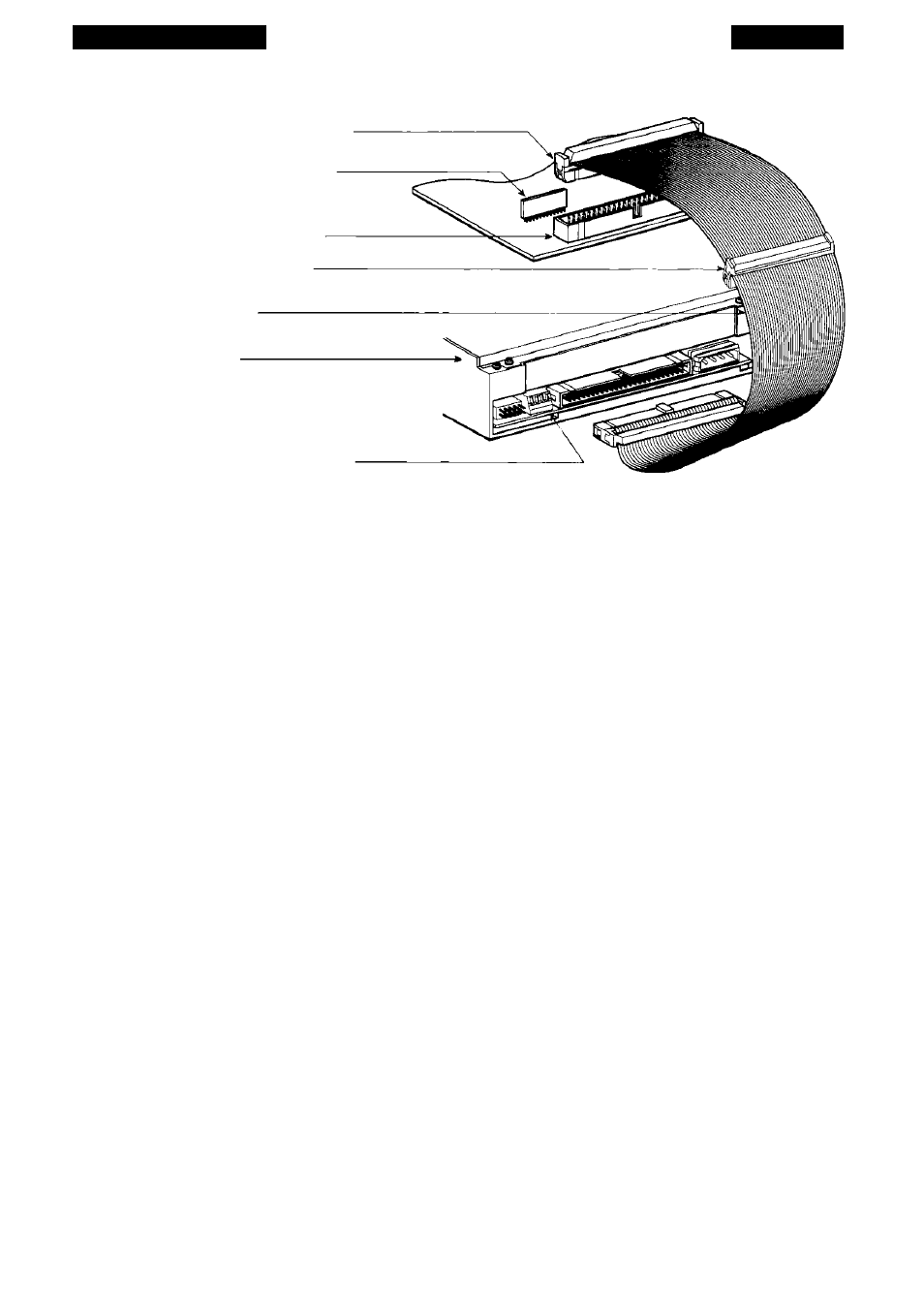
(a) Computer SCSI Controller
Computer Internal
SCSI Termination
Computer
SCSI Connector
Unused center
SCSI Connector
(b) SCSI Cable
(c) Coolscan
SCSI termination
switch is #4 (closest to 50 pin connector)
Figure 3.15 The PC’s internal SCSI Bus. (a) The PC’s SCSI controller card connecror. (b)
Inrernal SCSI cable, (c) Coolscan.
Procedure (use the supplied 3-connector 50-pin flat SCSI cable):
1. Make sure that the PC is powered off.
2. Connect one end of the flat SCSI cable to the PC’s SCSI connector, making sure
that they are properly aligned (see “Installing Coolscan Into the Drive Bay” in
Chapter Four for detailed description).
3. Connect the other end of the flat SCSI cable to the SCSI connector on the back
of Coolscan, making sure that the connectors are properly aligned (see “Installing
Coolscan Into the Drive Bay” in Chapter Four for detailed description).
In this case, both the SCSI host side of the bus and the SCSI target device side of
the bus must be terminated. Refer to the section “Terminating the SCSI Chain - LS-
10” in this chapter for the proper DIP switch setting.
Connecting Multiple SCSI Devices
In many cases, more than one SCSI target device will be connected to the SCSI
bus. When this is true, the chain of SCSI cables must connect or ‘daisy chain’ each
device together, even though the devices will typically only communicate directly with
the PC, not with each other. In this example, shown in Figure 3.16, Coolscan is placed
at the end of the SCSI chain. This daisy chaining configuration, minimizes the number
of cables and connectors required.
Page 34
Nikon
Coolscan Installation Guide for Windows