The guide rails, Procedure 4.1 - mounting the guide rails – Nikon LS-10 Installation Guide for Windows User Manual
Page 47
Attention! The text in this document has been recognized automatically. To view the original document, you can use the "Original mode".
Mounting the LS-10
Chapter 4
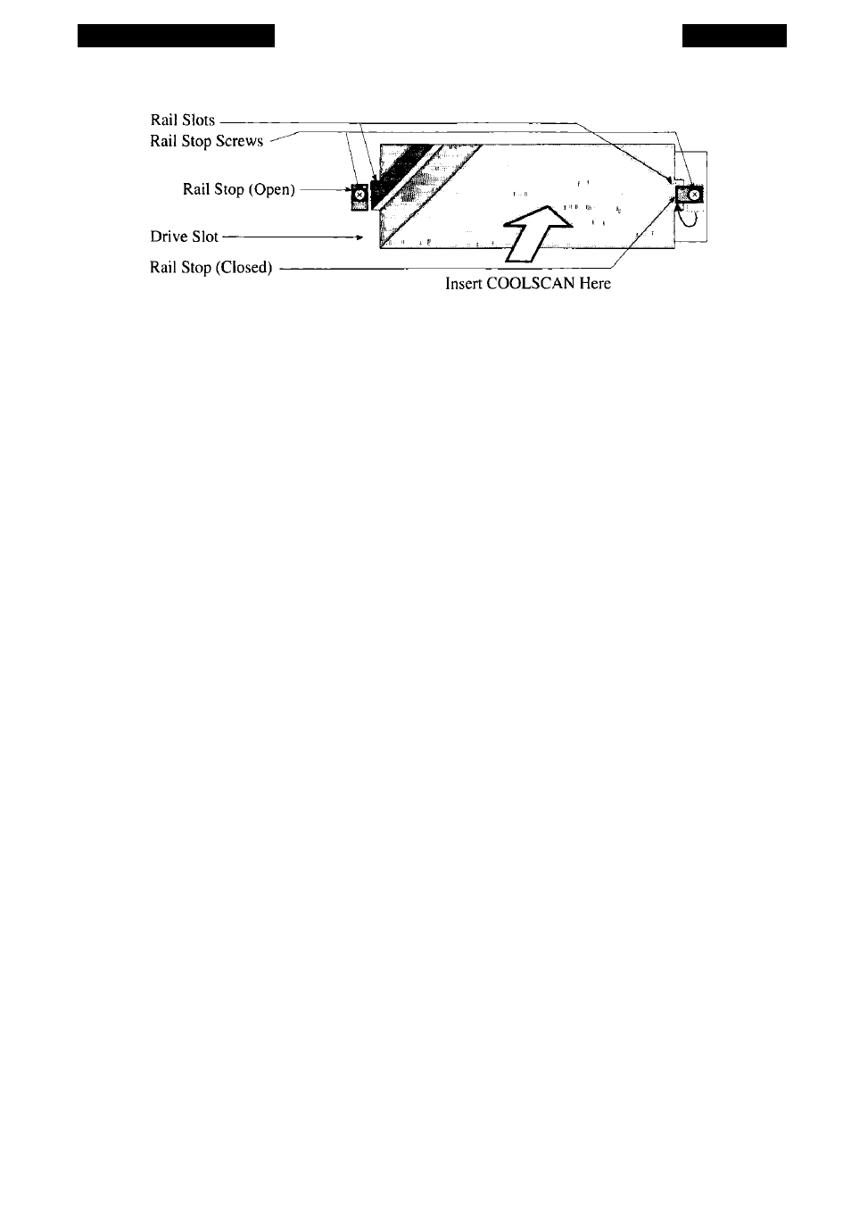
Figure 4.1 K
typical PC 5-1/4" half-height drive bay, as seen from the front of the computer.
The Guide Rails
Because each computer may have special requirements for mounting devices into
its drive bays, Nikon has included a versatile PC Mounting Kit. The pair of guide rails
included in this kit are connected with screws to the sides of the scanner, allowing it to
slide easily into the drive bay. These guide rails are also used to lock the scanner in
place.
There is no strict convention regarding the mounting of devices into the drive
bays. Consequently, the scanner and rails must provide a degree of installation flexibili
ty. This flexibility is provided by the two sets of tapped holes In the sides of the scanner
and two sets of elongated holes in the guide rails. You will need to select the proper
holes depending on the design of your computer’s drive bay.
Follow Procedure 4.1 for mounting the guide rails to the sides of Coolscan. Bear
in mind, it may require several attempts to determine the best combination for optimal
mounting.
Procedure 4.1 -
Mounting the Guide Rails
Step 1. Power off the PC and unplug its AC power cord. Also, power off all devices
connected to the PC.
Step 2. Disconnect the monitor cable connected to the back of the PC. Move the
monitor safely aside.
Step 3. Place the PC on a grounded, padded anti-static surface and orient it so that
you can easily remove its cover.
Page 40
Nikon
Coolscan Installation Guide for Windows