Orientation and placement of the ls-10e, Proper orientation, Orientation and placement of the ls-loe – Nikon LS-10 Installation Guide for Windows User Manual
Page 15
Attention! The text in this document has been recognized automatically. To view the original document, you can use the "Original mode".
Setting Up Coolscon
Chapter 2
The significance of the SCSI connector, DC power connector, and the configura
tion DIP switch is discussed in greater detail in Chapter 3, “The SCSI Interface.” For
now, note that the scanner is set at the factory to SCSI ID #5 and to termination OFF.
Disregard the external connector 3X the bottom-left side of Figure 2.3. This connector is
not used when installing the LS-10.
DIP Switch
Default
Usage
1 (Down)
On
SCSI ID bit 0 = 1
2 (Up)
Off
SCSI ID bit I = 0
3 (Down)
On
SCSI ID bit 2 = 1
4 (Up)
Off
SCSI Termination = Off
Table 2.1
Factory default settings for configuration DIP switch block.
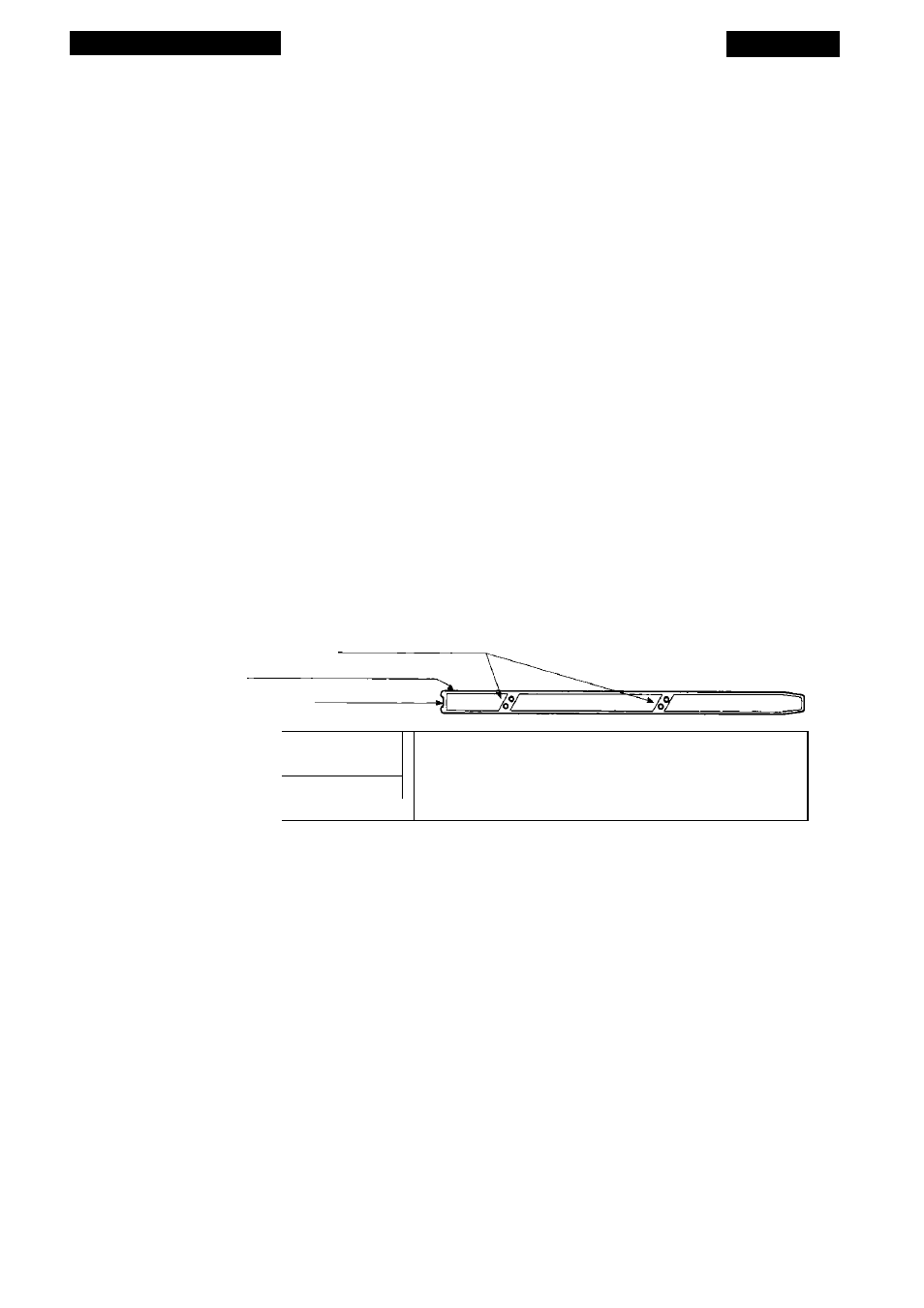
Both sides of the LS-10 are identical. Note the set of two tapped holes on each
side, called mounting holes, as shown in Figure 2.4. One set of mounting holes on each
side of the scanner will be used for the internal guide rails. This procedure will be
explained in detail in Chapter 4.
Mounting Holes
Guide Rail
Locking Tab
Top Panel
LS-10 Front Panel
Tapped Holes
o o
i
c
---------- ^ _____________________________
Figure 2.4
LS-10 - side view, with guide rails.
Please proceed to the section “Transporting Coolscan.”
Orientation and Placement of the LS-10E
Page 8
Proper Orientation
The following guidelines and precautions should be adhered to when deciding on
orientation of your LS-IOE.
Let’s take a look at Coolscan, as shown in Figure 2.5. Although Coolscan can be
oriented on either of its sides, it is strongly recommended that you orient Coolscan on
Nikon
Coolscan Installation Guide for Windows