Technical information – Rockwell Automation 20D PowerFlex 700S with Phase I Control Reference Manual User Manual
Page 28
28
Rockwell Automation Publication PFLEX-RM002D-EN-E - August 2013
Chapter 1
Detail Drive Configuration and Operation
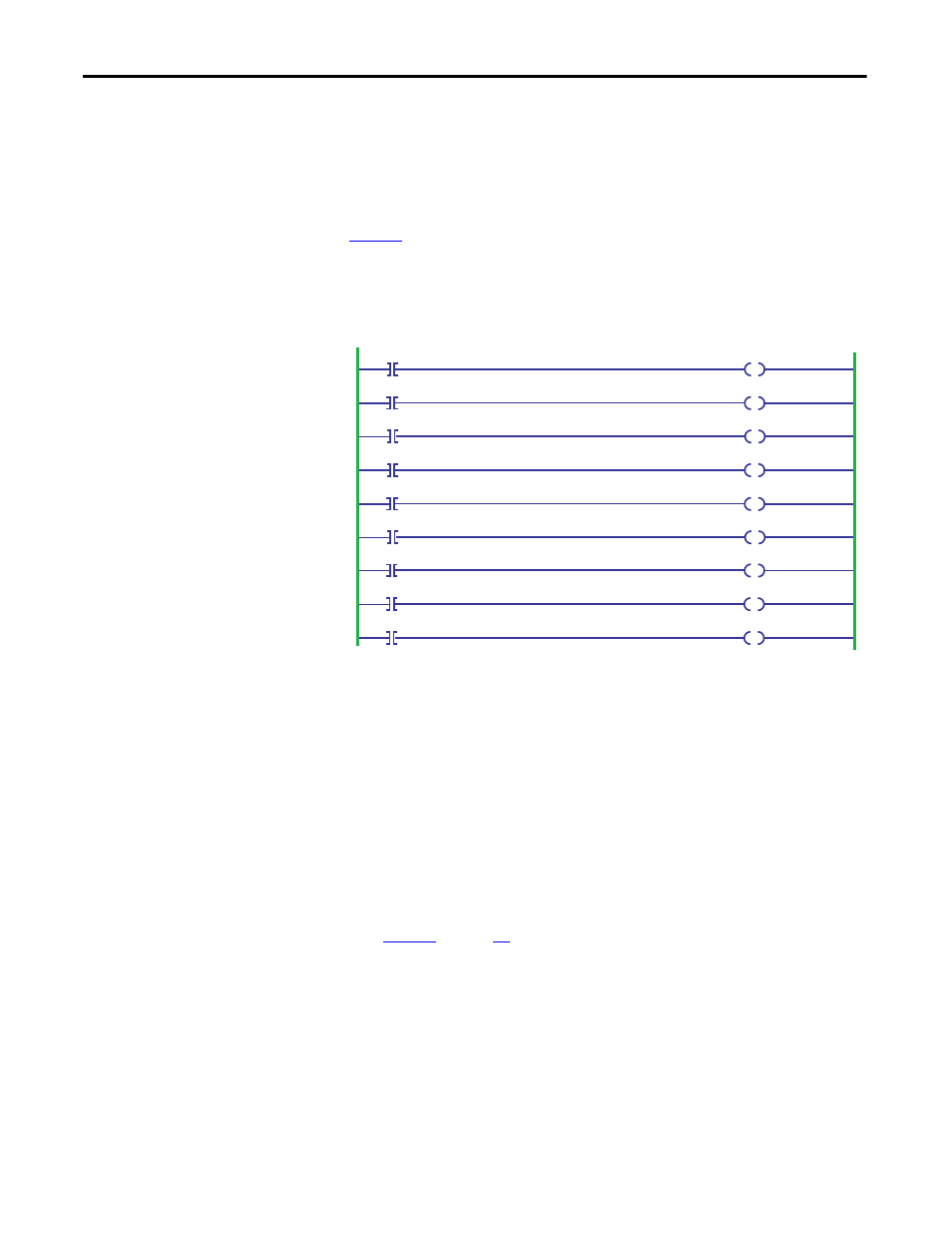
Example:
Tag names:
Outputs to the Drive - PowerFlex700S_02:O[0] … [9]
Inputs from the Drive - PowerFlex700S_02:I[0] … [10] word [0] reserved
Figure 3
is an example using Bits in the ControlLogix processor to write to the
output bits associated to parameter 158 [Drive Logic Rslt]
PowerFlex700S_02:O[0].0….9 map to parameter 158 [Drive Logic Rslt]
Figure 3 - Using Bits in ControlLogix
Technical Information
To use the 20-COMM-C with the PowerFlex 700S, the 20-COMM-C must be
v1.003 firmware or later.
The Logic Command and Logic Status are 32 bit data, but only the first 16 are
used. The bit definitions of the Logic Command word follow the same pattern as
parameter 158 [Drive Logic Rslt]. The bit definitions of the Logic Status word
follow the same pattern as bits 0-15 of parameter 155 [Logic Status].
Reference and Feedback are 16 bit unsigned integer data. Datalinks are 32 bit
data.
Figure 4
on page
29
shows I/O Image table for a ControlLogix system.
I.Data[0] is reserved.
PF700S_Coast Stop
PF700S_CurrLim_Stop
PF700S_Clear_Fault
PF700S_UniPol_Fwd
PF700S_UniPol_Rev
PF700S_Jog2
PF700S_Jog1
PF700S_Start
PF700S_Normal_Stop
PowerFlex700S_02:0.Data[0].1
PowerFlex700S_02:0.Data[0].0
PowerFlex700S_02:0.Data[0].8
PowerFlex700S_02:0.Data[0].7
PowerFlex700S_02:0.Data[0].5
PowerFlex700S_02:0.Data[0].3
PowerFlex700S_02:0.Data[0].2
PowerFlex700S_02:0.Data[0].9
PowerFlex700S_02:0.Data[0].4