Time axis generator – Rockwell Automation 20D PowerFlex 700S with Phase I Control Reference Manual User Manual
Page 179
Rockwell Automation Publication PFLEX-RM002D-EN-E - August 2013
179
Detail Drive Configuration and Operation
Chapter 1
Two Position Floating Point Switch
Configuration:
•
Parameter 1370 [Switch Control] bit 2 “SW Real 1 On” activates the
switch.
•
The value of parameter 1374 [SW Real 1 NO] is moved into parameter
1376 [SW Real 1 Output] when bit 2 “SW Real 1 On” of parameter 1370
[Switch Control] is on.
•
The value of parameter 1375 [SW Real 1 NC] is moved into parameter
1376 [SW Real 1 Output] when bit 2 “SW Real 1 On” of parameter 1370
[Switch Control] is off.
•
[SW Real 1 Output] contains the value of either [SW Real 1 NO] or [SW
Real 1 NC].
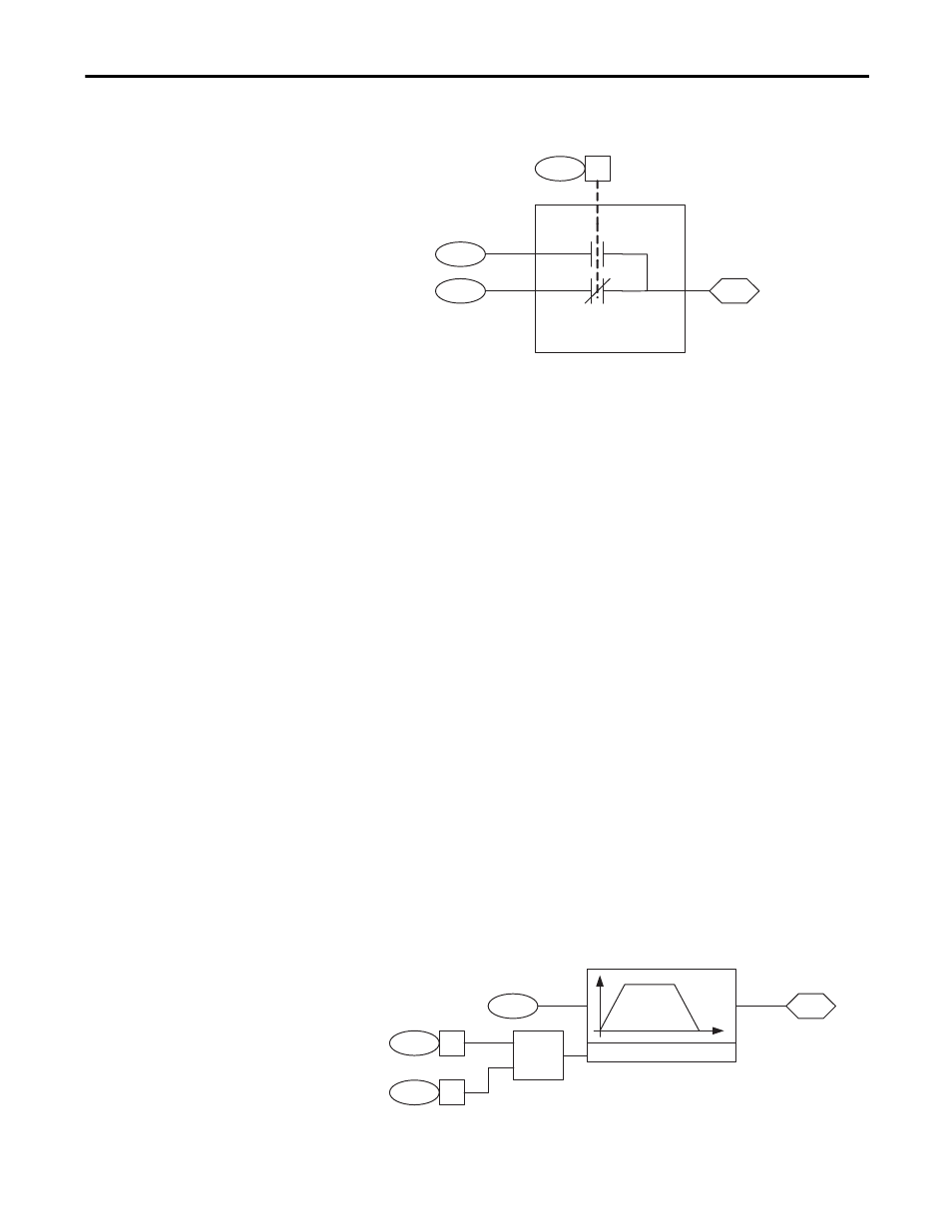
Time Axis Generator
Ramps the output of the function generator at the rate in parameter 200 [Time
Axis Rate].
•
When parameter 183 [PI Command] bit 1 “Time Lim En” or parameter
151 [Logic Command] bit 3 “Time Axis En” = 1 the output ramps from
0.0000…1.0000 at the Time Axis Rate set in [Time Axis Rate].
•
When parameter 183 [PI Command] bit 1 “Time Lim En” or parameter
151 [Logic Command] bit 3"Time Axis En” = 0 the output ramps from
1.0000…0.0000 at the Time Axis Rate set in [Time Axis Rate].
1371
1372
1370
1
1
0
1373
Switch Control
(SW Int 1 On)
SW Int 1 NO
SW Int 1 NC
SW Int 1 Output
OR
200
201
Time Func Generator
PI Command
(Time Lim En)
Logic Command
(Time Axis En)
Time Axis Rate
Time Axis Output
183
1
151
3