Rockwell Automation 20D PowerFlex 700S with Phase I Control Reference Manual User Manual
Page 166
166
Rockwell Automation Publication PFLEX-RM002D-EN-E - August 2013
Chapter 1
Detail Drive Configuration and Operation
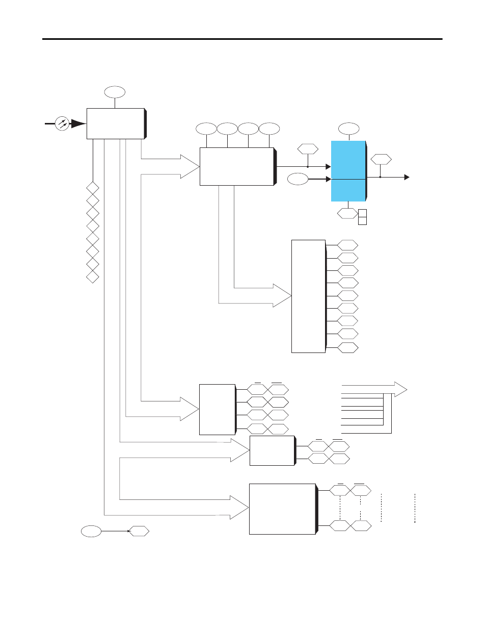
Figure 37 - Sync hLink Receive Block Diagram
5
Rx Format
Selector
1010
(0-17)
Rx Port Comm Format
Synchlink
Receive Port
Data (Rx) to
Upstream
Node
SycnhLink
Fiber
6
7
8
9
10
11
12
Rx Direct
Data
Selector
1011
1014
1012
1013
0
1
2
3
Direct Rx Data Select
(0-10)
1030
(sel = 1)
SL Mult A In
(sel = 2-10)
Event
Latches
(Upstream)
1040
2
10
9
8
7
6
5
4
3
Rx P0 Register
Rx Opt 1 Regis
Rx Opt 0 Regis
Rx D3 Latch
Rx D2 Latch
Rx D1 Latch
Rx D0 Latch
Rx P1 Register
Receive Events
1031
SL Mult B In
1033
(sel = 1)
SL Mult A In
Tx Multiply Data
(sel = 2-10)
Buffered
Receive
Data
Coordinated
System
Time
1054
1058
1060
1055
1059
1061
SL Dir (type) Rx 0
SL Dir (type) Rx 3
SL Dir (type) Rx 2
SL Dir (type) Rx 1
Int
Real
1070
1072
1069
1071
SL Buf (type) Rx 00
SL Buf (type) Rx 01
Int
Real
1074
1132
1073
1131
SL Buf (type) Rx 02
SL Buf (type) Rx 31
Int
Real
64 Parameters
1226
SL Comm TP Sel
SL Comm TP Data
Available for
Tx
"passthrough
data"
1
0
Local Overflow
Rx Overflow
AxB
SynchLink
Multipy
1032
SL Mult Base
Rx Axis Size
Rx Index 1
Rx Index 0
Rx Seq Cnt
Rx Pkg Size
Rx Buff Size
Rx Dir Size
Rx Index 2
1227
1041
1042
1045
1043
1044
1046
1047
1048
1034
1056
1057
See Table 1 on page 12 of SynchLink System Spec.
Defines number of Axis, Buffered & Direct words.