Direct data, Figure 36 - synchlink transmit block diagram – Rockwell Automation 20D PowerFlex 700S with Phase I Control Reference Manual User Manual
Page 165
Rockwell Automation Publication PFLEX-RM002D-EN-E - August 2013
165
Detail Drive Configuration and Operation
Chapter 1
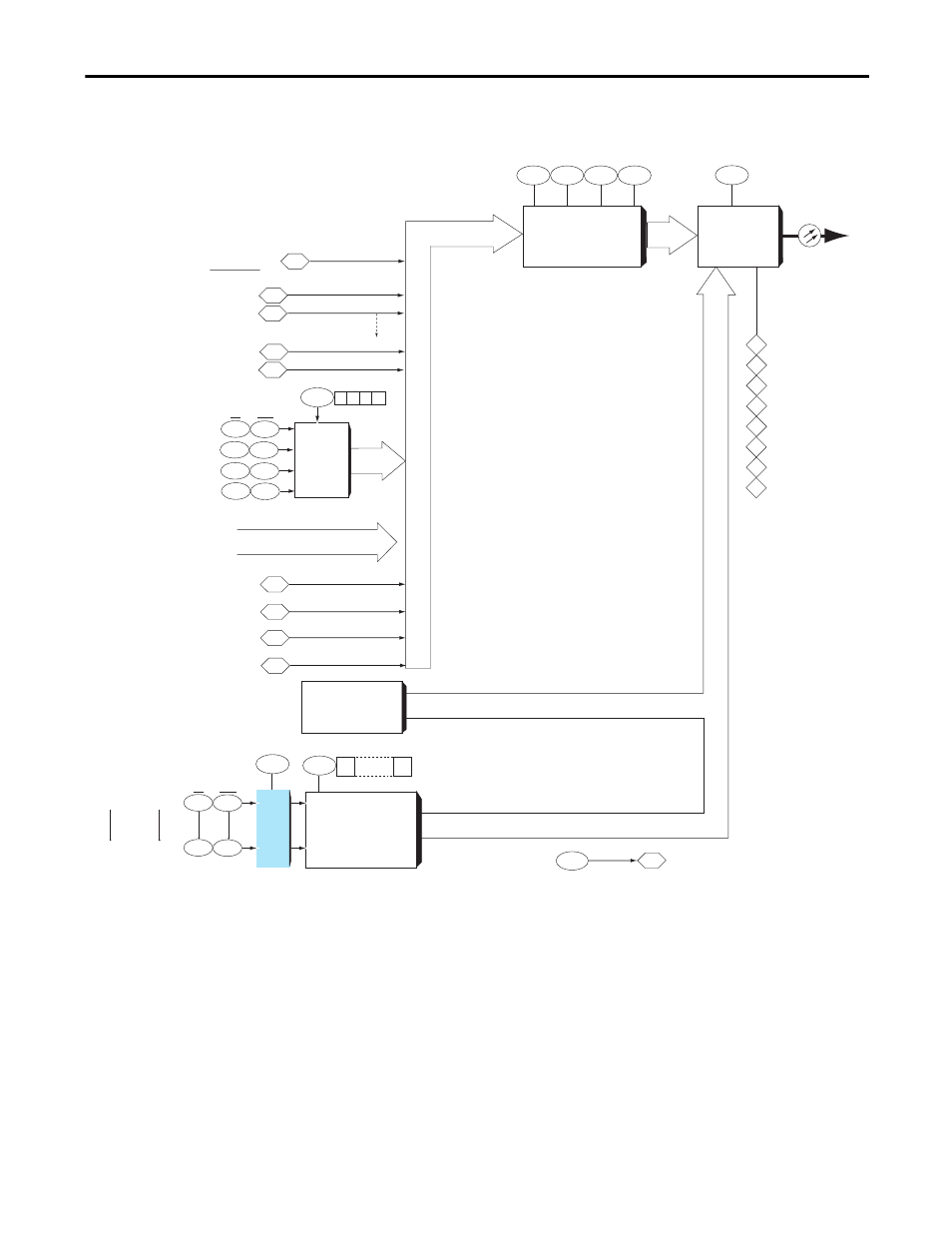
Figure 36 - SynchLink Transmit Block Diagram
1033
Tx
Direct Data
Selector
Tx Format
Selector
1021
1020
1024
1022
1023
0
1
2
3
Direct Tx Data Select
(0-26)
(0-17)
Tx Port Comm Format
235
245
Event Data
Registration Latches (Local)
253
XXX
(Select = 2)
(Select = 3)
(Select = 8)
1140
(Select = 9) "Not Used"
Direct
Transmit
Data
1147
1148
1145
1146
1143
1144
1141
1143
Int
Real
(Select = 21)
3 2
1 0
Tx Dir Data Type (1=Real)
(Select = 22)
Direct
'passthrough'
Data from Rx
230
240
250
XXX
Coordinated
System
Time
Buffered
Transmit
Data
1160
31
0
1161
1162
Int
Real
1020
1219
1220
Axis and
Buf config.
SL Buf (type) Tx02
SL Buf (type) Tx31
Tx Port Comm Format
Tx Buf Data Type (1 = real)
Buffered Transmit Data
1226
1227
SL Comm TP Sel
SL Comm TP Data
Direct Data
15
16
17
18
19
20
21
22
Synchlink
Transmit Port
Data (Tx) to
Downstream
Node
SycnhLink
Fiber
Tx Axis Size
Tx Index 1
Tx Index 0
Tx Seq Cnt
Tx Pkg Size
Tx Buff Size
Tx Dir Size
Tx Index 2
SL Dir (type) Tx0
SL Dir (type) Tx1
SL Dir (type) Tx2
SL Dir (type) Tx3
P0 Regis Latch
P1 Regis Latch
Opt 0 Regis Ltch
Opt 1 Regis Ltch
Encoder 0 Accum
Encoder 1 Accum
Opt 0 Accum
Opt 1 Accum
(Select = 23)
(Select = 24)
(Select = 25)
(Select = 26) "Not Used"