Rockwell Automation 20D PowerFlex 700S with Phase I Control Reference Manual User Manual
Page 140
140
Rockwell Automation Publication PFLEX-RM002D-EN-E - August 2013
Chapter 1
Detail Drive Configuration and Operation
•
Bit 9 “Edge Time” configures the method of sampling used by the Velocity
Position Loop (VPL). Setting the bit chooses “Edge to Edge” sampling,
while resetting the bit to zero chooses “Simple Difference” sampling.
“Simple Difference” sampling calculates speed by examining the difference
between pulse counts over a fixed sample time. “Edge to Edge” sampling
adjusts the sample time to synchronize with the position count updates
from the daughter card - improving the accuracy of the speed calculation.
•
Bits 12 “SmplRate bt0” through 15 “SmplRate bt3” configure the sample
interval for measuring speed (see
Table 7
on page
140
). Increasing the
encoder sample interval improves speed measurement near zero speed.
Decreasing allows the speed control regulator to perform with high gains
at high speeds.
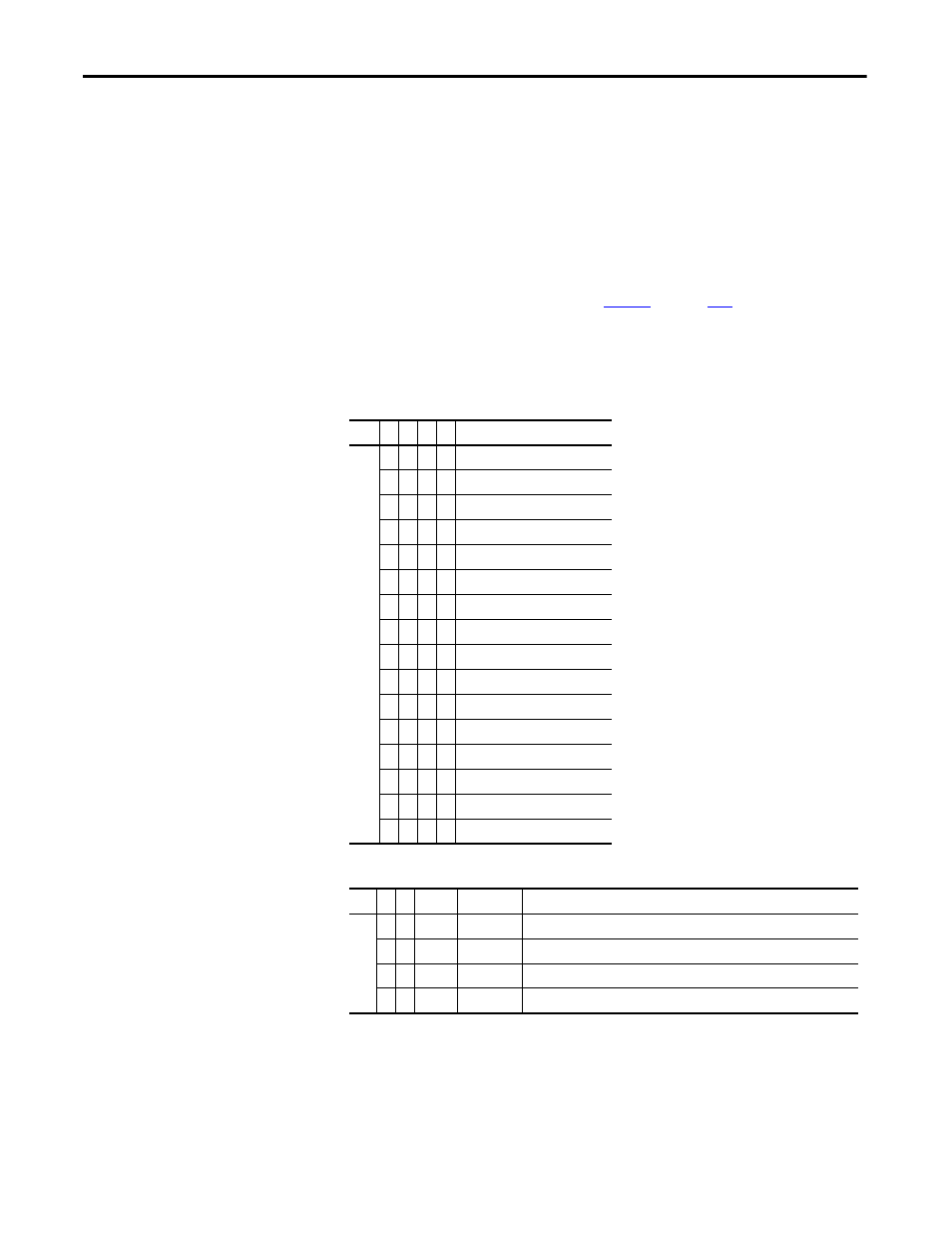
Table 7 - Encoder Input Filter Settings
Table 8 - Multiplier and Direction Settings
Bit
3
2
1
0
Encoder Bit Filter Settings
0
0
0
0
Filter disabled
0
0
0
1
100 ns filter
0
0
1
0
200 ns filter
0
0
1
1
300 ns filter
0
1
0
0
400 ns filter
0
1
0
1
500 ns filter
0
1
1
0
600 ns filter
0
1
1
1
700 ns filter
1
0
0
0
800 ns filter (default setting)
1
0
0
1
900 ns filter
1
0
1
0
1000 ns filter
1
0
1
1
1100 ns filter
1
1
0
0
1200 ns filter
1
1
0
1
1300 ns filter
1
1
1
0
1400 ns filter
1
1
1
1
1500 ns filter
Bit
5
4
Mult.
Directions
Comments
0
0
2x
fwd/rev
Counts rise/fall of phase A, phase B only used to find direction
0
1
4x
fwd/rev
Counts rise/fall of both A and B phases (default setting)
1
0
1x
fwd only
Counts rise of phase A. Phase B ignored.
1
1
2X
fwd only
Counts rise of phase A. Phase B ignored.