Thermal regulator, Torque reference, Torque reference input – Rockwell Automation 20D PowerFlex 700S with Phase I Control Reference Manual User Manual
Page 175: Thermal regulator torque reference, E torque reference
Rockwell Automation Publication PFLEX-RM002D-EN-E - August 2013
175
Detail Drive Configuration and Operation
Chapter 1
Thermal Regulator
See Drive Overload on page
Torque Reference
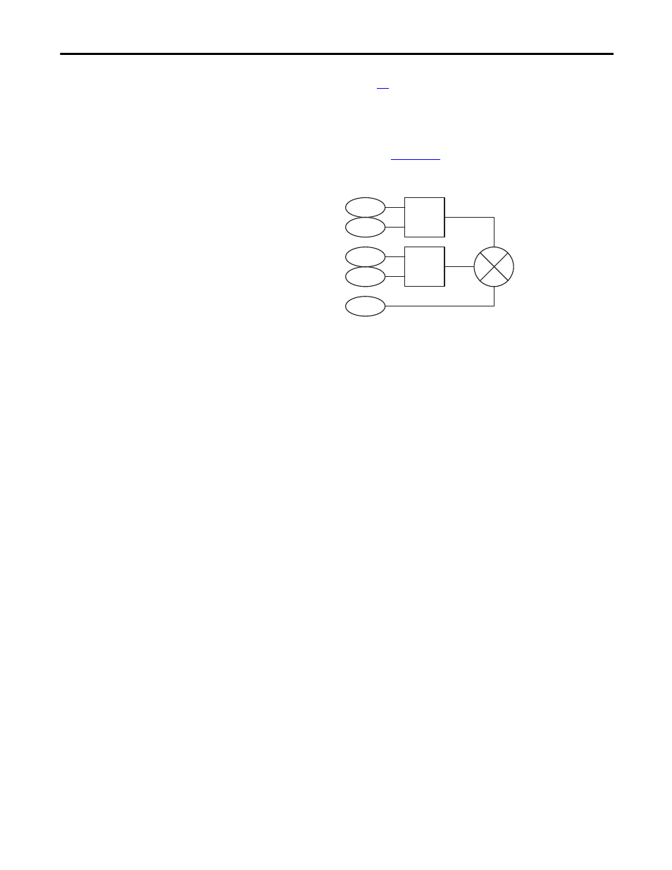
When the PowerFlex 700S is operated in Torque mode, an external signal is used
for a Torque reference. Refer to
Figure 38 -
for the firmware diagram.
Figure 38 - Torque Reference Firmware Diagram
Torque Reference Input
Parameter 111 [Torque Ref 1] is used to supply an external reference for desired
torque. The scaling of this parameter is a per unit type, where a value of 1.0 is
equal to the rated motor torque. The range is from -2200000000 to
+2200000000.
[Torque Ref 1] is then divided by parameter 112 [Torq Ref1 Div]. This defines
the scaled [Torque Ref 1].
Parameter 113 [Torque Ref 2] is used to supply an external reference for desired
torque. The scaling of this parameter is a per unit type, where a value of 1.0 is
equal to the rated motor torque. The range is from -2200000000 to
+2200000000.
[Torque Ref 2] is then multiplied by parameter 114 [Torq Ref2 Mult]. This
defines the scaled [Torque Ref 2].
The torque reference can be utilized when a master/slave multi-drive system is
configured. The torque reference into the “slave” can be scaled to create the
proper torque output. Keep in mind that the motors may be different ratings and
this function is used to help the “system” share the load.
Parameter 115 [Torque Trim] can be used to trim the torque.For example,
[Torque Trim] can be limited to an analog input or to the Process PI output.
Once the scaling is complete on both [Torque Ref 1] and [Torque Ref 2], the
output is summed with the output of the [Torque Trim].
111
X
112
113
114
115
/
+
+
+
Torque Ref 1
Torque Ref1 Div
Torque Ref 2
Torque Ref2 Mult
Torque Trim