Analog output configuration, Example configuration 1 – Rockwell Automation 20D PowerFlex 700S with Phase I Control Reference Manual User Manual
Page 16
16
Rockwell Automation Publication PFLEX-RM002D-EN-E - August 2013
Chapter 1
Detail Drive Configuration and Operation
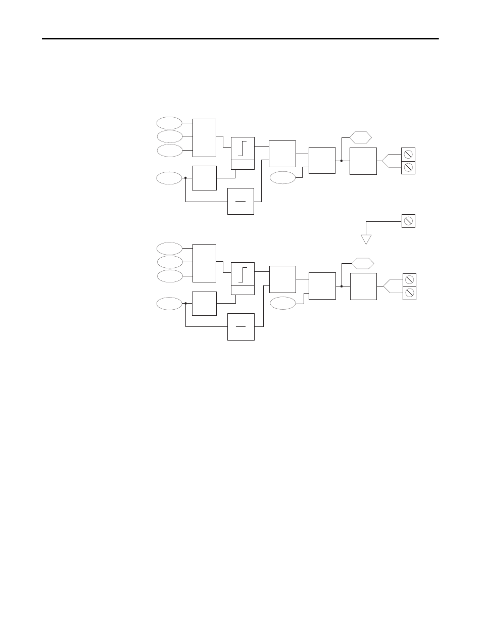
Analog Output Configuration
The analog outputs can be linked to either an integer parameter or a real
parameter. Use [Anlg Outx Real] when you are linking to a real parameter and
use [Anlg Outx Integer] when you are linking to an integer parameter.
[Anlg Outx Offset] is added to [Anlg Outx Real] or [Anlg Outx Integer] before
the scaling and limiting blocks. [Anlg Outx Offset] has a range of +/-20V.
The result of [Anlg Outx Offset] plus [Anlg Outx Real] or [Anlg Outx Integer]
is limited by 10 times the value of [Anlg Outx Scale].
Then that limited value is divided by the value of [Anlg Outx Scale].
[Anlg Outx Zero] is added after the scaling and limiting of the analog output
value. [Anlg Outx Zero] can be used to null out any offset from the D/A
converter.
Example Configuration 1:
This configuration sends the motor torque current reference value to a 0-10V
analog output signal.
•
[Anlg Out1 Real] is linked to [Mtr TrqCurr Ref ]
•
[Anlg Out1 Scale] = 0.1 per Volt
TB1-B5
TB1-B6
-
+
816
X
Anlg Out1 Volts
818
812
814
815
817
+
Anlg Out1 Zero
Anlg Out1 Offset
Anlg Out1 Integer
Anlg Out1 Real
Anlg Out1 Scale
D/A
12bit
1
[x]
Limit
+
10 [x]
TB1-B5
TB1-B6
-
+
816
X
Anlg Out1 Volts
823
813
819
820
822
+
Anlg Out1 Zero
Anlg Out2 Offset
Anlg Out2 Integer
Anlg Out2 Real
Anlg Out2 Scale
D/A
12bit
1
[x]
Limit
+
10 [x]
TB1-B4
Shield