Speed pi regulator, Speed trim, Speed pi regulator o – Rockwell Automation 20D PowerFlex 700S with Phase I Control Reference Manual User Manual
Page 120
120
Rockwell Automation Publication PFLEX-RM002D-EN-E - August 2013
Chapter 1
Detail Drive Configuration and Operation
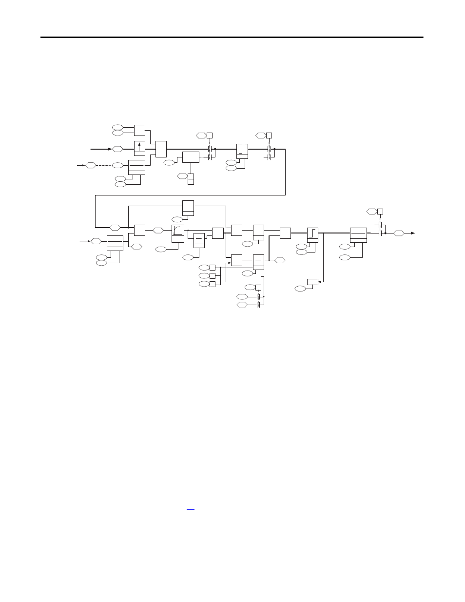
Speed PI Regulator
The drive takes the speed reference specified by the speed reference control loop
and compares it to the speed feedback. The speed regulator uses proportional
and integral gains to adjust the torque reference sent to the motor. This torque
reference attempts to operate the motor at the specified speed. This regulator also
produces a high bandwidth response to speed command and load changes.
Figure 32 - Overview of the Speed PI Regulator Loop
The main purpose of the speed PI regulator is to produce a torque reference for
the current regulator block. The following section will describe each portion of
the speed PI regulator.
Speed Trim
The speed trim blocks are used to sum the speed reference from the speed
reference control loop with speed trim values from other sources.
[Spd Trim1 SpdRef ] contains the value of the speed reference from the speed
reference control loop plus the value from [Speed Trim 1]. [Speed Trim 1] is
setup by default to come from the process PI loop.
Parameter 22 [Speed Trim 2] provides a trim value with a lead/lag filter that is
added to [Spd Trim1 SpdRef ]. By default, it is linked to the output of the
position loop. For more information on lead/lag filters, see to Lead-Lag Filter on
page
.
Parameter 23 [Speed Trim 3] provides a scalable speed trim value that is added to
[Spd Trim1 SpdRef ]. The speed reference value for [Speed Trim 3] is multiplied
by the scaling parameter 24 [Spd Trim 3 Scale]. [Spd Trim 3 Scale] is a linkable
25
26
22
+
X
23
24
0
Autotune
Bypass
19
157
5
8
157
04
30
31
93
94
89
+
85
84
81
82
80
01
153
12
+
102
103
95
96
157
08
0
86
Droop
47
318
301
71
300
100
101
302
Ovr Smpl
4x
0
1
157
06
0
Logic Ctrl State
Atune Spd Ref
Limit
Logic Ctrl State
(Inrta Tst En)
Logic Ctrl State
(CurrLim Stop)
Speed Trim 3
SpdTrim 3 Scale
Spd Trim1 SpdRef
Speed Trim 2
STrim2 Filt Gain
SpdTrim2 Filt BW
ServoLck
ks
s
P Gain
kp
I Gain
ki
s
80
02
80
03
Limit
Spd Reg P Gain
Spd Reg I Gain
0
1
87
303
Spd Reg Pos Lim
Spd Reg Neg Lim
FeedFwd
nff
SReg FB Filt Gain
SReg FB Filt BW
Filtered SpdFdbk
Motor Spd Fdbk
Motor Speed Ref
Speed Error
SpdReg AntiBckup
Spd Err Filt BW
Servo Lock Gain
Control Options
(Jog -NoInteg)
Speed Reg Ctrl
(Integ Hold)
Speed Reg Ctrl
(Integ Reset)
Speed Reg Ctrl
(Preset Sel)
SReg Torq Preset
Motor Torque Ref
Spd Reg Droop
0
1
SRegOut FiltGain
SReg Out Filt BW
Logic Ctrl State
(Spd Reg En)
Spd Reg PI Out
Posit Spd Output
*
from Speed Control
- Reference [2H4]
from Position
Control [6H3] or [7H4]
to Torque Control
[4A1]
2
nd
Order
LPass
Filter
SpdReg Integ Out
(J Tst FulSpd)
(Spd Reg En)
1
from Feedback [9H2]
+
-
+
-
+
-
Lead Lag
(kn * s)+ wn
s + wn
Lead Lag
(kn * s)+ wn
s + wn
Lead Lag
(kn * s)+ wn
s + wn