Application example, Analog inputs, Analog input specifications – Rockwell Automation 20D PowerFlex 700S with Phase I Control Reference Manual User Manual
Page 14: Analog input configuration
14
Rockwell Automation Publication PFLEX-RM002D-EN-E - August 2013
Chapter 1
Detail Drive Configuration and Operation
Application Example:
Parameter 376 [Inv Ol Pend Cnfg] is set to a value of 1 “Alarm”. This configures
the drive to set the alarm bit, parameter 326 [Alarm Status 1] bit 15 “Inv OL
Pend” when the inverter overload pending event occurs. This alarm will allow the
drive to continue running. The user can make the decision as to what action to
take in relation to the alarm.
Analog Inputs
Analog Input Specifications
There are 2 analog inputs located on TB1 - Row B (Bottom Terminals). Each
input accepts a +/-10V or +/-1V bipolar, differential signal. Dip switches SW1-1
and SW1-2 are used to select whether the analog inputs are +/-10V or +/-1V.
The A/D converter is 14 bits including the sign bit (13 bits plus the sign bit).
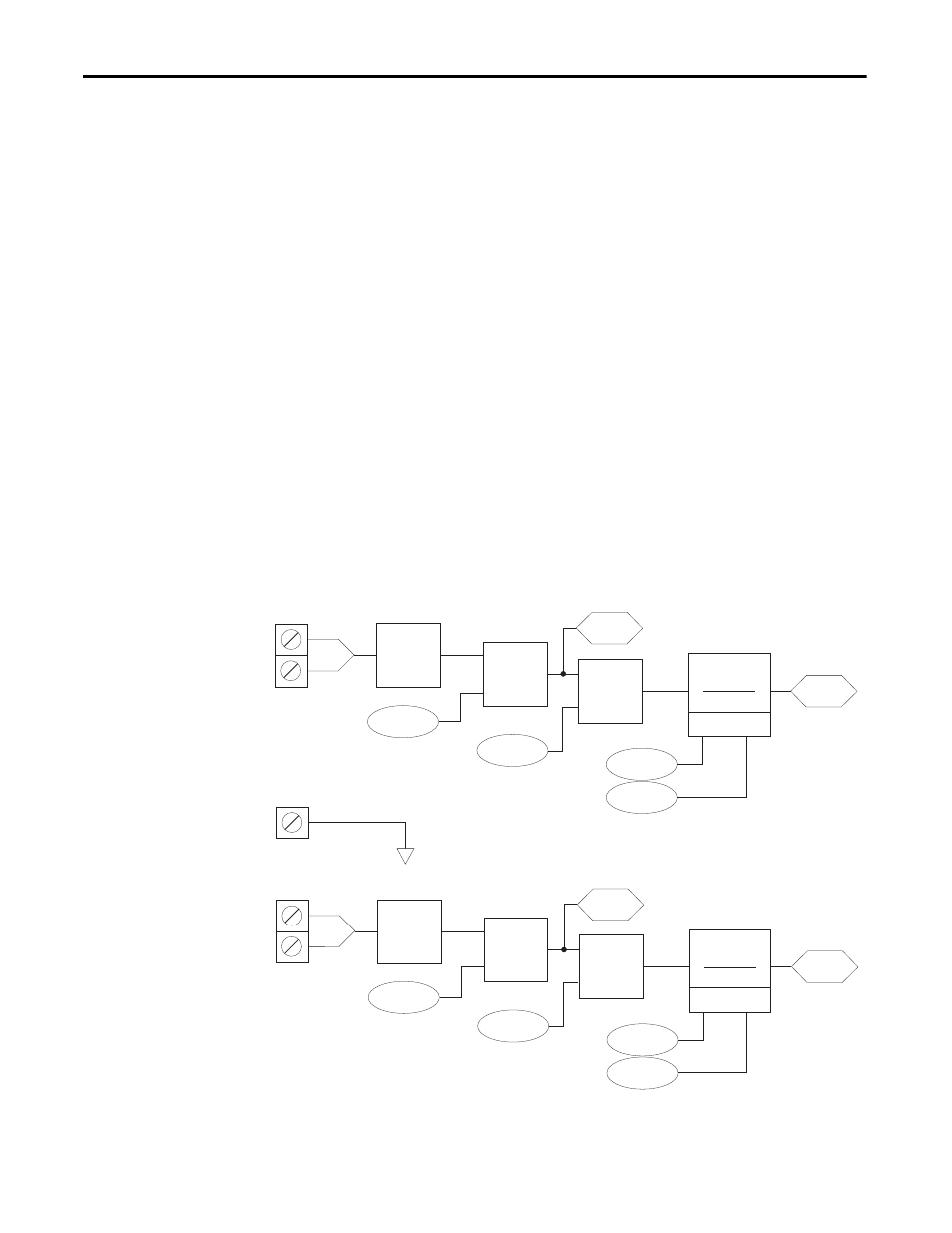
Analog Input Configuration
Once the Analog Input is converted, [Anlg Inx Offset] can be applied. This
parameter has a range of +/-20V. [Anlg Inx Volts] is the sum of the A/D output
and [Anlg Inx Offset]. [Anlg Inx Volts] are displayed as +/-10V.
[Anlg Inx Scale] scales [Anlg Inx Volts] to the range of [Anlg Inx Data]. A
destination parameter, such as a speed reference can then be linked to [Anlg Inx
Data].
[AIx Filt Gain] and [Anlg Inx Filt BW] are used to filter the analog input data.
A/D
14bit
803
802
804
805
TB1-B11
TB1-B10
-
+
Anlg ln1 Offset
Anlg ln1 Scale
+
X
Anlg ln1 Volts
Lead Lag
(kn * s) + wn
s + wn
800
Anlg ln1 Data
Al 1 Filt Gain
Anlg ln1 Filt BW
801
A/D
14bit
809
808
810
811
TB1-B8
TB1-B7
-
+
Anlg ln2 Offset
Anlg ln2 Scale
+
X
Anlg ln2 Volts
Lead Lag
(kn * s) + wn
s + wn
806
Anlg ln2 Data
Al 2 Filt Gain
Anlg ln2 Filt BW
807
Shield
TB1-B9