Chapter summary – Rockwell Automation 1794-OF8IH FLEX Isolated Input/Output HART Analog Modules User Manual
Page 88
Publication 1794-UM065B-EN-E - September 2010
76 1794-IF8IH and 1794-OF8IH Configuration
The Module supports six states, common to all Phase 1 EDT compliant
modules, as described below. A single bi-color indicators the module status as
indicated below.
Chapter Summary
In this chapter, you learned how to configure your HART module and how to
use the RSLogix software to install and configure your module. The next
chapter describes how to configure your module to automatically collect data
from the HART field device and place it in the module's Input Tag.
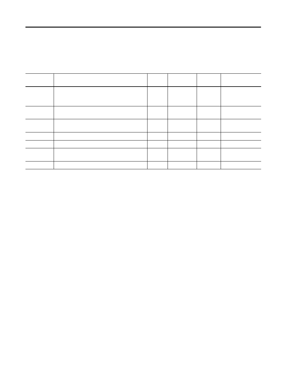
Module Status Indicators
Module
State
Condition
PU Bit
Prog/Run bit
Fault bit
LED Color and
State
New
Power up initialized complete and passed Self-Test.
Loads stored configuration, if it exists. Read Module
Information Block.
(1)
*
(2)
*
*
Red, blink @ 1 Hz
No Config
Module has not received configuration from Master.
It can Set and Get attributes.
0
*
*
Green, blink @ 1 Hz
Idle
Controller in Program mode.
Communications normal
1
0
1
Green, blink @ 1 Hz
Active
Controller in Run mode & Communication Is normal
1
1
1
Green, solid
Fault
FLEX I/O Comm. Fault or PU bit is one and /Fault=0
*
*
0
Green, blink@ 1 Hz
Fatal fault
Module fails self tests or detects illegal state
transition
*
*
*
Red, solid
Off
External power has not been applied.
Off
(1)
The status bits in the table correspond to module status bits available in the module status word.
(2)
Bit state flagged as '*' depends on the state transition, per FLEX I/O Systems Specifications.