Rockwell Automation 1794-OF8IH FLEX Isolated Input/Output HART Analog Modules User Manual
Page 45
Publication 1794-UM065B-EN-E - September 2010
1794-IF8IH and 1794-OF8IH Configuration 33
5
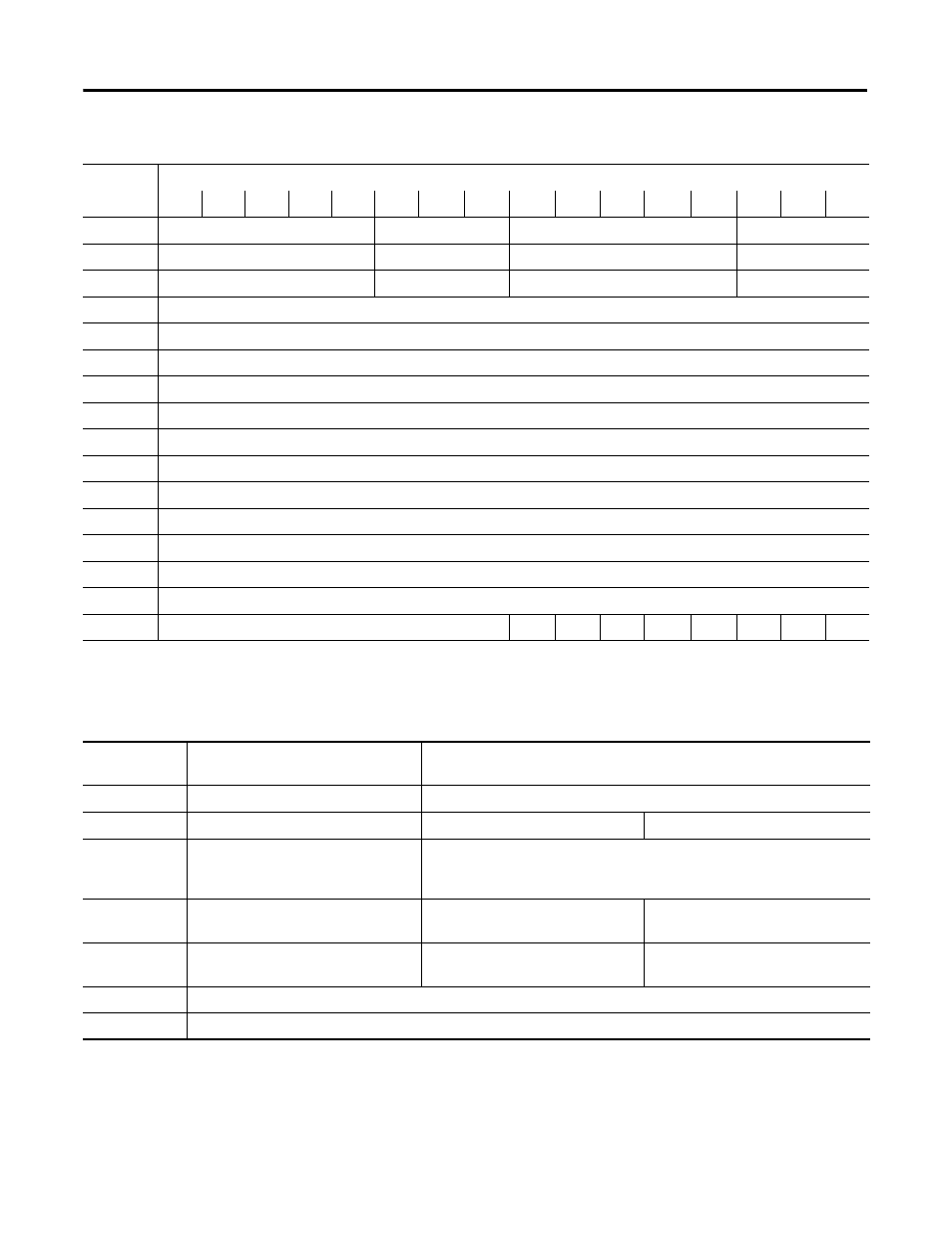
CH3 HART Current Ratio
FLTR3
CH2 HART Current Ratio
FLTR2
6
CH5 HART Current Ratio
FLTR5
CH4 HART Current Ratio
FLTR4
7
CH7 HART Current Ratio
FLTR7
CH6 HART Current Ratio
FLTR6
8
Reserved
9
CH0 High Alarm threshold
10
CH0 Low Alarm threshold
11
CH0 Remote High High Alarm Limit
12
CH0 Remote Low Low Alarm Limit
13…16
Words 9…12 for Channel 1
17…20
Words 9…12 for Channel 2
21…24
Words 9…12 for Channel 3
25…28
Words 9…12 for Channel 4
29…32
Words 9…12 for Channel 5
33…36
Words 9…12 for Channel 6
37…40
Words 9…12 for Channel 7
41
Reserved
C7
C6
C5
C4
C3
C2
C1
C0
(1)
not shown or used in RSLogix 5000.
(2)
reserved data may not be shown in certain controller software
Configuration Map Descriptions
BOA
BOB
Byte order group A
Byte order group B
Byte order group A and B values must match each other.
Refer to the Byte Order table on page 37.
FLTRn
Channel n Digital Filter
Refer to 1794-IF8IH Channel Digital Filter table
Fn
Fault mode channel n
0: Local/Remote faults disabled
1: Enabled
CHn HART
Current Ratio
HART current fault ratio limit on
channel n
Valid values are 0, or 5…31 percent of full scale. A value of 0 disables this
feature. Refer to the 1794-IF8IH HART Current Ratio table on page 34 for more
information.
DHn
Disable HART communications on
channel n
0: HART communications enabled
1: HART communications disabled
Cn
HART CMD 3 Disable
0: HART CMD 3 communications
enabled
1: HART CMD 3 communications
disabled
R
Reserved
CH N Format
Refer to the 1794-IF8IH Channel Data Formats table on page 34.
Configuration Parameters
Word
Bit
15
14
13
12
11
10
9
8
7
6
5
4
3
2
1
0