Fault mode (8 of 1 bit) – Rockwell Automation 1794-OF8IH FLEX Isolated Input/Output HART Analog Modules User Manual
Page 76
Publication 1794-UM065B-EN-E - September 2010
64 1794-IF8IH and 1794-OF8IH Configuration
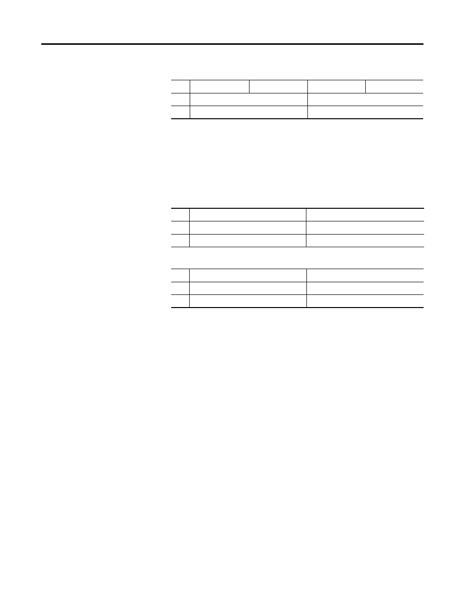
Provide all data to the Primary Data table in Word Swap byte order, except the
MSW and EDT words (Words 0, 1 and 15), these remain in Little Endian byte
order.
The following tables are an example of the Primary Input Data, if BYTE
ORDER indicated Word Swap.
Default: 0
Fault Mode (8 of 1 bit)
Selects whether the channel fault detection is enabled or disabled. There is a
100 ms filter for wire off/lead break and short circuit detection.
Range: 0=Disable, 1= Wire off/ead break and short circuit fault detection
enabled.
Default: 0
Bus Communications and Module Fault Mode (1 of 1 bit)
This parameter determines how the Module Fault State is used for bus
communication and internal module faults. This parameter sets this
characteristic for the module.
Range: 0=Fault States activated by bus communication faults, 1=Fault States
activated by any failure (bus communications, wire off or short circuit if
detection enabled, for example.)
Partial Configuration Assembly After BYTE ORDER Inspection and Processing
1
Param A Ch2
Param B Ch2
Param A Ch1
Param B Ch1
2
Param C CH0 (2nd byte)
Param C CH0 (low byte)
3
Param C CH0 (high byte)
Param C CH0 (3rd byte)
Primary Input Data Before BYTE ORDER Processing for Little Endian
1
Ch2 Data A (REAL) (2nd byte)
Ch2 Data A (REAL) (low byte)
2
Ch2 Data A (REAL) (high byte)
Ch2 Data A (REAL) (3rd byte)
3
Ch2 Data C
Ch 2 Data B
Primary Input Data After BYTE ORDER Processing for Little Endian
1
Ch2 Data A (REAL) (high byte)
Ch2 Data A (REAL) (3rd byte)
2
Ch2 Data A (REAL) (2nd byte)
Ch2 Data A (REAL) (low byte)
3
Ch2 Data C
Ch 2 Data B