Latch mode (8 of 1 bit each), Analog/digital output mode (8 of 1 bit each) – Rockwell Automation 1794-OF8IH FLEX Isolated Input/Output HART Analog Modules User Manual
Page 79
Publication 1794-UM065B-EN-E - September 2010
1794-IF8IH and 1794-OF8IH Configuration 67
Latch Mode (8 of 1 bit each)
Latch Mode determines channel operation under wire off/lead break fault
conditions. Channel fault detection occurs on a continuous basis. If a fault is
detected, the channel fault alarm is set (if Fault Mode is enabled).
If latch is ON the fault is latched until a Global Reset is issued at which time
the fault is reset.
If latch is OFF the channel reports the fault until the fault is corrected. Upon
correction the fault is reset.
Range: 0=OFF, 1=ON
Default: 0
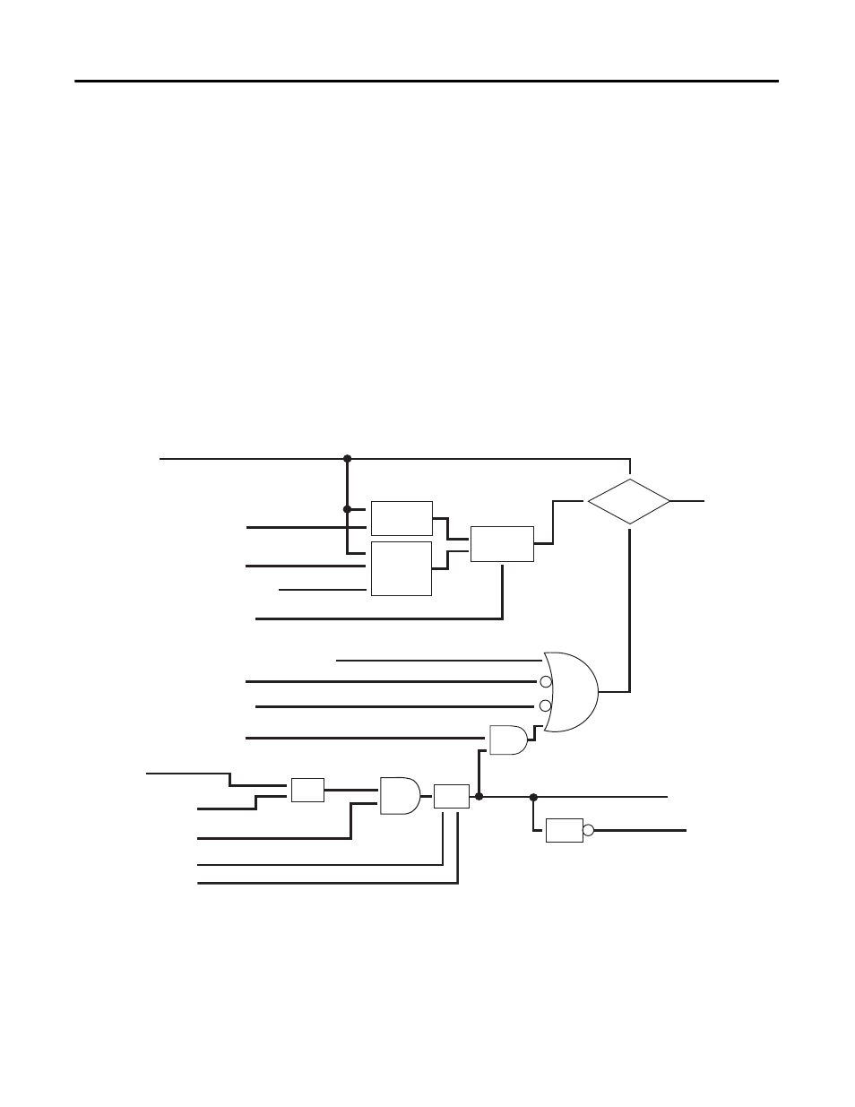
Analog/Digital Output Normal and Fault State Operation
Analog/Digital Output Mode (8 of 1 bit each)
Selects if the channel acts as a normal analog output or as a switched digital
output.
Reset
Hold Last
MIN Range
MAX Range
Hold Last
Fault State Value
Normal State
Value
Fault State
Value
Fault
Latch
Mode
100 ms
Filter
Blink
Timer
Reset
Output Mode
(Analog/Digital)
45287
FAULT_ALARM_0
FAULT_LED_0
CHANNEL_0
GLOBAL_RESET
LATCH_MODE_0
FAULT_MODE_0
SHRT_CRKT_0
LB_0
LOCAL_FAULT_MODE_0
PROG/RUN (EDT word Bit 15)
FAULT (EDT word Bit 14)
BUS_COM_FAULT, other internal module faults
ANALOG_DIGITAL_MODE_0
ANALOG_FAULT_STATE_0
DIGITAL_FAULT_STATE_0
OUT_0
ANALOG_FAULT_STATE_VALUE_0