Fault mode (8 of 1 bit) – Rockwell Automation 1794-OF8IH FLEX Isolated Input/Output HART Analog Modules User Manual
Page 50
Publication 1794-UM065B-EN-E - September 2010
38 1794-IF8IH and 1794-OF8IH Configuration
Word Swap BYTE ORDER
If BYTE ORDER indicates Word Swap, utilize the known structure of the
configuration assembly to re-order multi-word data elements to Little Endian
byte order, for example, word swap FLOATS).
Provide all data to the Primary Data table in Word Swap byte order, except the
MSW and EDT words (Words 0, 1 and 15), these remain in Little Endian byte
order.
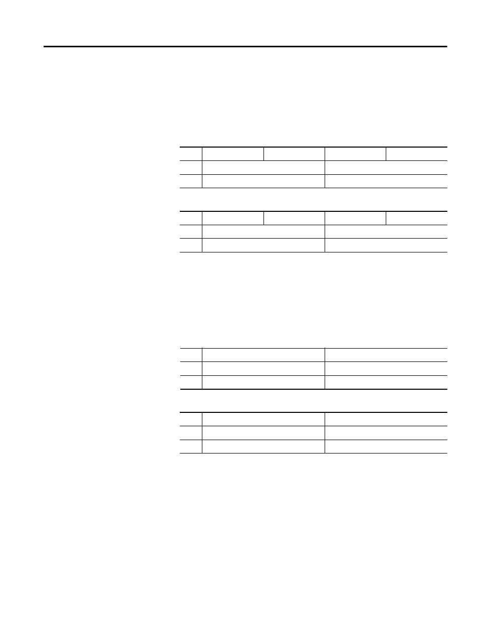
The following tables are an example of the Primary Input Data, if BYTE
ORDER indicated Word Swap.
Fault Mode (8 of 1 bit)
Selects whether the channel fault detection for Local and Remote Alarms is
enabled or disabled. This does not disable High and Low Alarms.
Range: 0=disable, 1=fault detection enabled (remote transmitter loop, wire off
and overload or short circuit)
Default: 0
Data Table Reference: fault mod, Configuration Word 0, Bits 2…5 and
10…13.
Partial Configuration Assembly as Received
1
Param A Ch2
Param B Ch2
Param A Ch1
Param B Ch1
2
Param C CH0 (high byte)
Param C CH0 (3rd byte)
3
Param C CH0 (2nd byte)
Param C CH0 (low byte)
Partial Configuration Assembly after BYTE ORDER Inspection and Processing
1
Param A Ch2
Param B Ch2
Param A Ch1
Param B Ch1
2
Param C CH0 (2nd byte)
Param C CH0 (low byte)
3
Param C CH0 (high byte)
Param C CH0 (3rd byte)
Primary Input Data Before BYTE ORDER Processing for Little Endian
1
Ch2 Data A (REAL) (2nd byte)
Ch2 Data A (REAL) (low byte)
2
Ch2 Data A (REAL) (high byte)
Ch2 Data A (REAL) (3rd byte)
3
Ch2 Data C
Ch 2 Data B
Primary Input Data After BYTE ORDER Processing for Little Endian
1
Ch2 Data A (REAL) (high byte)
Ch2 Data A (REAL) (3rd byte)
2
Ch2 Data A (REAL) (2nd byte)
Ch2 Data A (REAL) (low byte)
3
Ch2 Data C
Ch 2 Data B