1794-oe8h calibration flowchart procedure -18, 1794-oe8h calibration flowchart procedure 5-18 – Rockwell Automation 1794-OE8H FLEX I/O HART Analog Modules User Manual User Manual
Page 86
Publication 1794-UM063A-EN-P - March 2006
5-18 Calibrate Your Module
1794-OE8H Calibration Item Byte Value Identifier 48 (Status Mask
Calibration)
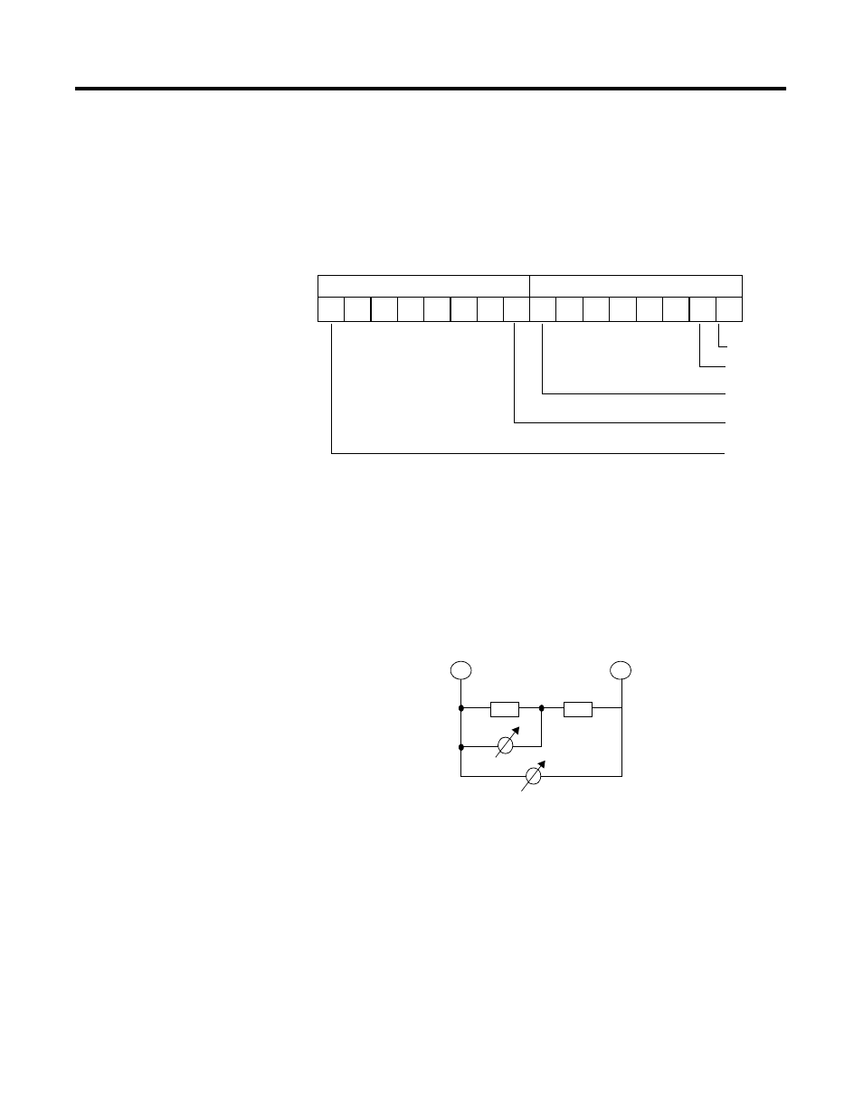
Each bit of the lower byte of this word corresponds to one channel. A logical 1
within the lower byte of the words means that this channel is completely
calibrated. A logical 0 means that this channel is not completely calibrated. In
an attempt to write the upper byte of this word, write 0x00h. In an attempt to
read the upper byte of this word, 0x00h is given back.
1794-OE8H Calibration Flowchart Procedure
Perform the calibration at ambient room temperature, 25(±5) °C, according to
the procedure flowchart. Each channel is calibrated one after the other. The
current is measured indirectly via a precision voltmeter placed across a
precision 100 W resistor.
Before all values are completely calibrated, a calibration error is displayed
within the Real Time Data field in the diagnostic status field. After calibration
is complete, the I/O module stores the calibrated values in the RAM area.
Therefore, you must send a store command to cause the I/O module
totransfer the RAM content to the EEPROM Therefore, you must send a
store command to cause the I/O module totransfer the RAM content to the
EEPROM.
15
14
13
12
11
10
9
8
Channel 0
7
6
5
4
3
2
1
0
Reserved
Offset
Channel 1
:
Channel 7
Reserved
Reserved
:
+
-
CHx
100
Ω
650
Ω
Voltmeter
Voltmeter