Data format -9, Data format – Rockwell Automation 1794-OE8H FLEX I/O HART Analog Modules User Manual User Manual
Page 33
Publication 1794-UM063A-EN-P - March 2006
Configurable FLEX I/O Analog Module Features 2-9
Data Format
You must choose a module data format in your user program. See
1794-OE8H Data Formats on page 2-10 for an explanation of each bit. Data
Formats 2, 5, 6, 8, 9, 10, 12 and 15 are not assigned.
When choosing a data format, remember the following:
• If an unassigned Analog Data Format is selected, the module sets
Diagnostic Data to 2 for configuration failure and puts affected
channels affected in the corresponding fault state.
• An unconfigured module channel pair can be assumed to have the
default configuration Analog Data Format 0, 0 to 20 mA and Analog
Mode Fault State minimum range. If a non-assigned format is selected,
then the diagnostic 2 for configuration failure is set and the module
channel pair goes to the default fault state minimum range.
• If on the other hand, the configuration had been changed, from the
default, and then it was changed again to a non-assigned format, then
the diagnostic bit 2 for configuration failure is set and the module goes
to the fault state for the last valid configuration.
• Formats 13 and 14 are 2’s complement data formats, and require data to
the module in that form.
• Range: 0 to 15
• Default: 0
• Data Table Reference: data format, word 12 and 13, bits 0 to 3,
bits 4 to 7
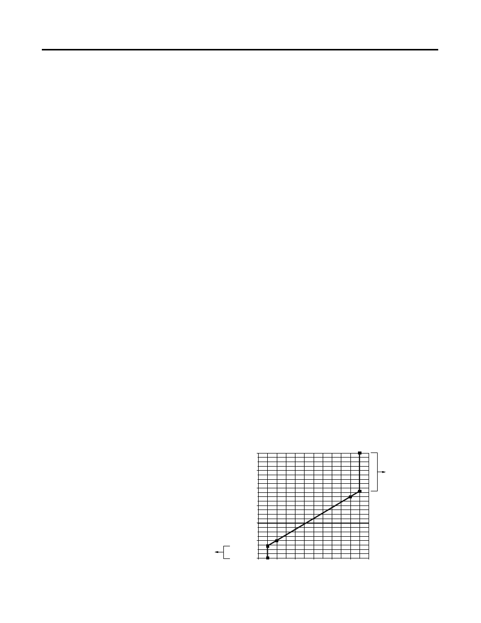
If data is sent to the module which is out of range, the value will be clipped and
Diagnostic Data will be set to 11 data out of range.
0
4
8
12
16
20
24
-4.000
0.000
4.000
8.000
12.000
16.000
20.000
Output mA
datatable
Diagnostic Data error
11=data out of range
Diagnostic Data error
11=data out of range