Bit/word description for the analog input module, 1794-ie8h) -14 – Rockwell Automation 1794-OE8H FLEX I/O HART Analog Modules User Manual User Manual
Page 38
Publication 1794-UM063A-EN-P - March 2006
2-14 Configurable FLEX I/O Analog Module Features
Bit/Word Description for the Analog Input Module
(1794-IE8H)
Table 2.8 Fault Mode - Write Words 0 and 1
Table 2.9 Add-on Filter Selections - Write Words 0 and 1
Table 2.10 Remote Transmitter Error Up/Down - Write Words 0 and 1
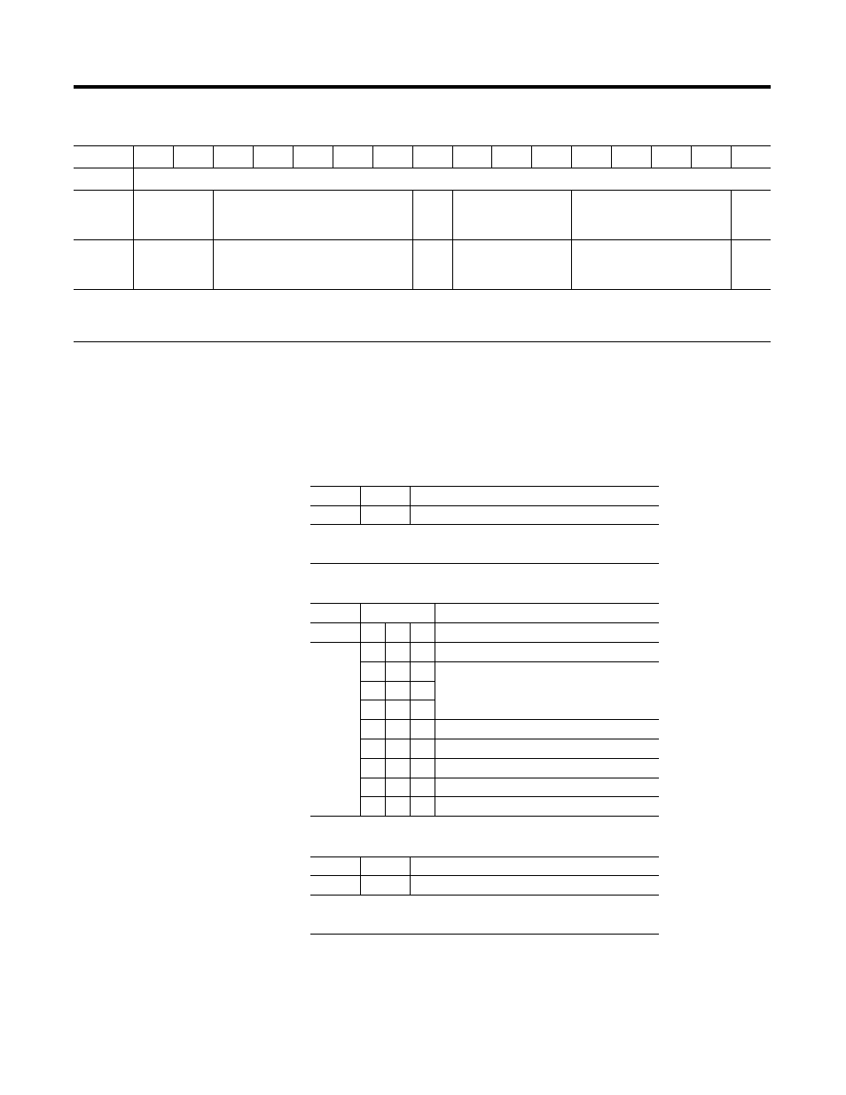
Table 2.7 Configuration Map (Write Words)
Bit
→
15
14
13
12
11
10
09
08
07
06
05
04
03
02
01
00
Word
↓
Write
0
Reserved
High and Low Error Level 0…3
U/D
0…3
Filter Cutoff 0…3
Data Format 0…3
Flt
Md
0…3
1
Sqrt
High and Low Error Level 4…7
U/D
4…7
Filter Cutoff 4…7
Data Format 4…7
Flt
Md
4…7
Where:
U/D = up/down
Flt Md = Fault Module
Sqrt = Square Root
Word 0
Bit 00
Fault enable for channels 0…3
Word 1
Bit 00
Fault enable for channels 4…7
Where:
0 = disabled
1 = enable with wire-off and overload or short circuit
Word
Bits
Description
0
07 06 05 Channels 0…3
1
07 06 05 Channels 4…7
0
0
0
Reserved - Module will not operate with
these settings.
0
0
1
0
1
0
0
1
1
10 Hz (100 ms)
1
0
0
4 Hz (250 ms)
1
0
1
2 Hz (500 ms)
1
1
0
1 Hz (1 s)
1
1
1
0.5 Hz (2 s)
Word 0
Bit 08
Up/down channels 0…3
Word 1
Bit 08
Up/down channels 4…7
Where:
0 = remote fault is enabled by transmitter overrange
1 = remote fault is enabled by transmitter underrange