Rockwell Automation 1794-OE8H FLEX I/O HART Analog Modules User Manual User Manual
Page 52
Publication 1794-UM063A-EN-P - March 2006
3-6 Install Your FLEX I/O Analog Modules
To install the mounting plate on a wall or panel:
1. Lay out the required points on the wall/panel as shown in the drilling
dimension drawing.
2. Drill the necessary holes for the #6 self-tapping mounting screws.
3. Mount the mounting plate (1) for the adapter module using two #6
self-tapping screws (18 included for mounting up to 8 modules and the
adapter).
4. Hold the adapter (2) at a slight angle and engage the top of the
mounting plate in the indention on the rear of the adapter module.
5. Press the adapter down flush with the panel until the locking lever locks.
6. Position the terminal base unit up against the adapter and push the
female bus connector into the adapter.
7. Secure to the wall with two #6 self-tapping screws.
8. Repeat for each remaining terminal base unit.
40871
1
3
2
4
+V
+V
-V
-V
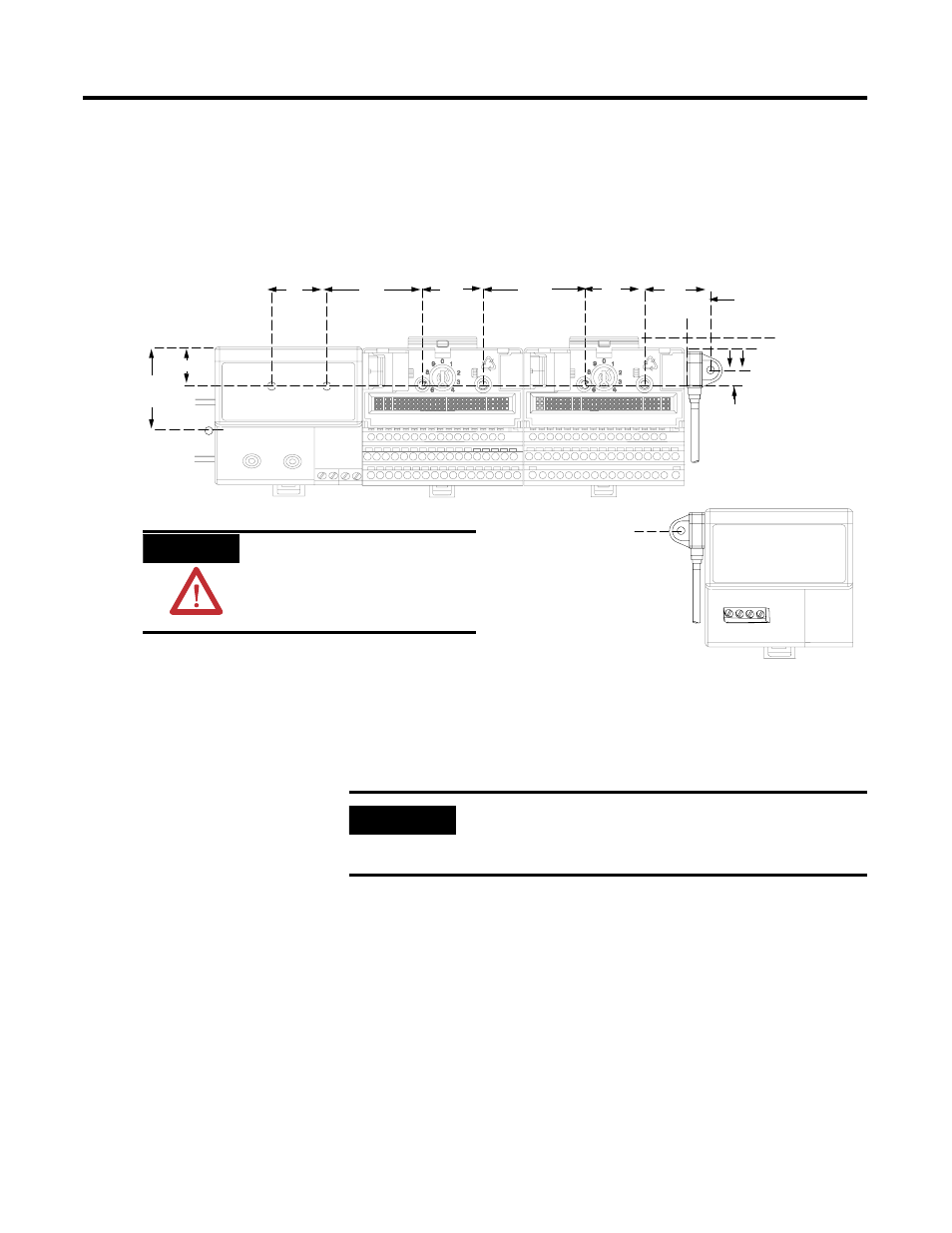
Drilling Dimensions for Panel/Wall Mounting of FLEX I/O
35.5
(1.4)
15.6
(0.61)
58.5
(2.3)
40.5
(1.6)
8
(0.3)
35.5
(1.4)
58.5
(2.3)
35.5
(1.4)
.83 (21)
50
(2.0)
mm (in.)
Cable length
approximately 292.1 mm
(11.5 in.) or 901.0 mm
(35.5 in.) from upper
connector. Length
depends upon cable 0.3 m
(1 ft) or 0.91 m (3 ft).
ATTENTION
ATTENTION
Be careful of metal chips when
drilling cable mounting holes. Do
not drill holes above a system that
has any modules installed.
IMPORTANT
Make certain that the mounting plate is properly grounded to
the panel. Refer to Industrial Automation Wiring and Grounding
Guidelines, publication 1770-4.1.