Rockwell Automation 1794-OE8H FLEX I/O HART Analog Modules User Manual User Manual
Page 39
Publication 1794-UM063A-EN-P - March 2006
Configurable FLEX I/O Analog Module Features 2-15
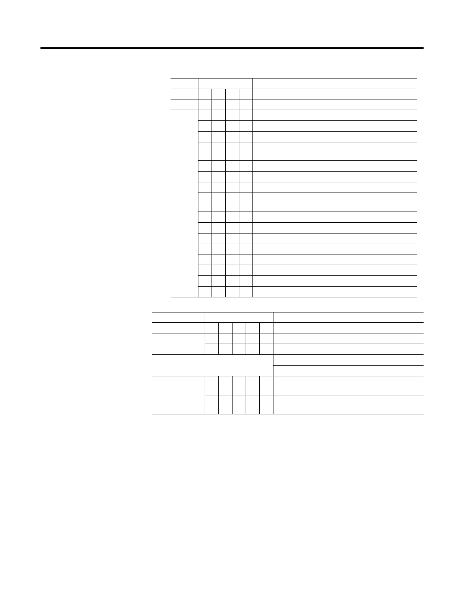
Table 2.11 Data Format - Write Words 0 and 1
Table 2.12 Error Level 0.1mA Steps
Bits
Description
Word 0
04 03 02 01 Data format for channels 0…3
Word 1
04 03 02 01 Data format for channels 4…7
0
0
0
0
0…22 mA, with error steps (default)
0
0
0
1
0…22 mA = 0…110%, with error steps
0
0
1
0
0…22 mA = 0…104.8%, square root, with error steps
0
0
1
1
0…22 mA = 0…65,535, unsigned integer, with error
steps
0
1
0
0
2…22 mA, w/error steps
0
1
0
1
2…22 mA = -12.5…112.5%, with error steps
0
1
1
0
4…22 mA = 0…106%, square root, with error steps
0
1
1
1
4…20 mA = 0…65,535, unsigned integer, with error
steps
1
0
0
0
Not assigned
1
0
0
1
Not assigned
1
0
1
0
Not assigned
1
0
1
1
0…22 mA = A/D count, with fixed error
1
1
0
0
3.6…21 mA = NAMUR NE 43, with fixed error
1
1
0
1
3…21 mA = -6.25…106.28% with fixed error
1
1
1
0
2…22 mA = -12.5…112.5% with fixed error
1
1
1
1
Not assigned
Bits
Description
Word 0
13 12 11 10 9
Error level channels 0…3
Word 1
13 12 11 10 9
Error level channels 4…7
0
0
0
0
0
Disabled
0.1mA * step value = remote fault alarm threshold
Examples
Data Format
2…22mA
-12.5…112.5%
0
0
1
1
1
Step value = 7, 0.1 mA * 7 = 0.7 mA
Remote fault alarm at -4.38% or +104.38%
0
1
1
1
1
Binary value = 15, 0.1 mA * 15 = 1.5 mA
Remote fault alarm at -9.38% or + 109.38%