Rockwell Automation 1794-OE8H FLEX I/O HART Analog Modules User Manual User Manual
Page 82
Publication 1794-UM063A-EN-P - March 2006
5-14 Calibrate Your Module
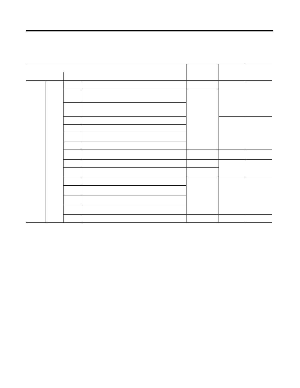
Table 5.11 1794-OE8H Interpretation of Calibration Data Structure Content During Read Access (Idle Status)
Command Byte
Item Byte
Data1 Byte
Data2 Byte
Status (Binary)
Command Bits 0…5 (Decimal)
00
Idle
0
Nothing is done. The state after power on.
0
0
0
1
The min scale value is supported at the outputs according
to channel-mask
Channel-mask
2
The max scale value is supported at the outputs
according to channel-mask
3
The written min scale value of Current was accepted
Value
low-byte
Value
high-byte
4
The written min scale value of Voltage was accepted
5
The written max scale value of Current was accepted
6
The written max scale value of Voltage was accepted
7
Reserved
(1)
Reserved
Reserved
Reserved
8
All calibration values are set to default
0
0
0
9
The specified calibration value is set to default
Value-identifier
10
Reserved
(2)
Reserved
Reserved
Reserved
11
Reserved
12
Reserved
13
Reserved
14
The calibration content is saved to EEPROM.
0
0
0
(1)
Do not use. Designated for future use.
(2)
Reserved. Used during manufacture of the product.