For two-wire transmitter devices – Rockwell Automation 1794-OE8H FLEX I/O HART Analog Modules User Manual User Manual
Page 55
Publication 1794-UM063A-EN-P - March 2006
Install Your FLEX I/O Analog Modules 3-9
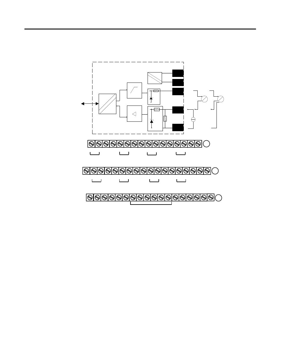
Connections for the 1794-IE8H HART Analog Input Module on a
1794-TB3G Terminal Base Unit
For Two-wire Transmitter Devices
1. Connect the individual input wiring to (+) terminals (0, 4, 8, 12) on the 0
to 15 row (A) and on the 16 to 33 row (B) (terminals 17, 21, 25, 29) as
indicated in the table below.
2. Connect the associated input to the corresponding (sig) terminal (1, 5, 9,
13) on the 0 to 15 row (A), and on the 16 to 33 row (B) (terminals 18,
22, 26, 30) for each input as indicated in the table below.
3. Connect +V dc power to terminal 34 on the 34 to 51 row (C).
4. Connect -V to terminal 35 on the 34 to 51 row (C).
40071
17 18 19 20 21 22 23 24 25 26 27 28 29 30 31 32 33
0 1 2 3 4 5 6 7 8 9 10 11 12 13 14 15
16
35 36 37 38 39 40 41 42 43 44 45 46 47 48 49 50 51
34
Chassis
Ground
(1794-TB3G shown)
Chassis
Ground
+V
-V (COM)
24C dc
Supply In
+V
-V (COM)
24C dc
Supply Out
Chassis Grounds for Shields
+V = +24V dc = Terminals C-34 and C-50
-V = COM = C-35 and C-51
Chassis Ground = Terminals B-16, B-33, C-38, C-40…45, and C-47
A
B
C
For daisy-chaining: Supply in - C-34 (+) and C-35 (-)
Supply out - C-50 (+) and C-51 (-)
NC = No connection
NC
NC
+
_
+
_
+
_
+
_
+
_
+
_
+
_
+
_
Ch0
Ch1
Ch3
Ch5
Ch2
Ch4
Ch6
Ch7
Flexbus
Bus
uC
+V
-V
+
Sig
-
4 to 20mA
Xmit
4 to 20mA
Xmit
I
P
P
I
40072
22
Ω
91
Ω
17V