Logic commands, Logic commands -18 – Rockwell Automation 2098-DSD-xxx Ultra3000 Digital Servo Drives with DeviceNet User Manual
Page 34
Publication 2098-RM004A-EN-P – August 2002
2-18
Programming Reference
Logic Commands
The first two or four bytes in several Output Assemblies are referred
to as the Logic Command. The logic command bits correspond to
functions available via the hardware digital inputs on the Ultra3000
Drive with DeviceNet. Parameter 10 - Logic Command Mask allows
you to mask off (zero) selected Logic Command bits to prevent the
bits activating any functions.
Note: The Logic Command Mask has a default value of zero.
Therefore, the Logic Command has no affect unless you modify
the Logic Command Mask.
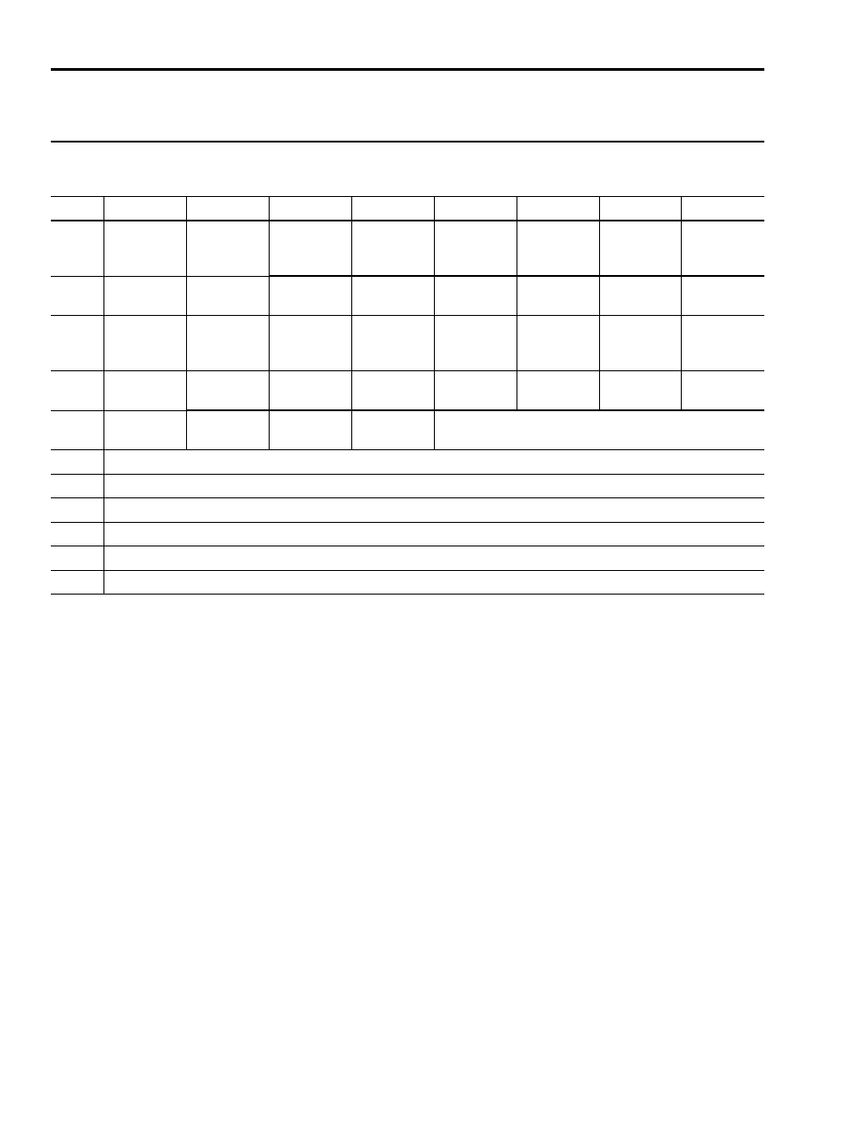
Assembly Object,
Instance ID = 9 - Output Assembly
32 Bit Logic Command, Startup Commutation Done Bit, Feedback Data Pointer, and Parameter Data Value
Byte
Bit 7
Bit 6
Bit 5
Bit 4
Bit 3
Bit 2
Bit 1
Bit 0
0
Reserved
Reserved
Reserved
1
Reserved
Reserved
2
Reserved
Reserved
Reserved
3
Enable
Reserved
4
Write Data
Save to
NVMEM
Reserved
5
Parameter Instance - Low Byte
6
Parameter Instance - High Byte
7
Data Value - Low Byte
8
Data Value - Low Middle Byte
9
Data Value - High Middle Byte
10
Data Value - High Byte