Rockwell Automation 1794-APB/B FLEX I/O PROFIBUS Adapter Module User Manual User Manual
Page 84
2–64
How Communication Takes Place and I/O Image Table Mapping
Publication 1794ĆUM057B-EN-P - November 2001
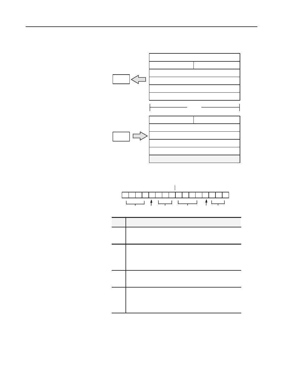
1203ĆFM1 - SCANport Module Image Table Mapping
0
Connection Status Channel 1
Logic Status Channel 1
Analog Feedback Channel 1
Logic Status Channel 2
Analog Feedback Channel 2
Connection StatusChannel 2
Module Image
I/O Image
6 Words
5 Words
Read
Write
1 Word
Connection Enable Channel 2 Connection Enable Channel 1
Logic Command Channel 1
Analog Reference Channel 1
Logic Command Channel 2
Analog Reference Channel 2
Not Used
Connection Status Word Definition
Connection Status Channel 2
Connection Status Channel 1
15 14 13 12 11 10 9 8 7 6 5 4 3 2 1 0
Bit:
Not Used V2
ID2
Not Used
V1
ID1
Description
V1
SCANport channel 1 valid data bit. When high (1), the Logic Status
and Analog Feedback values are valid and can be used. When low
(0), the values should not be used.
ID1
SCANport channel 1 connected peripheral port ID number. This three
bit field contains the port number that channel 1 is connected to on the
SCANport device. It should contain a value between 1 and 7. If this
field is 7, then the channel is not connected to the SCANport device, or
the SCANport device may not be powered.
V2
SCANport channel 2 valid data bit. When high (1), the Logic Status
and Analog Feedback values are valid and can be used. When low
(0), the values should not be used.
ID2
SCANport channel 2 connected peripheral port ID number. This three
bit field contains the port number that channel 2 is connected to on the
SCANport device. It should contain a value between 1 and 7. If this
field is 7, then the channel is not connected to the SCANport device, or
the SCANport device may not be powered.
Logic Status/Analog Feedback Definition
The Logic Status and Analog Feedback values are defined within the product
manuals of the connected SCANport device(s).