Polled i/o structure – Rockwell Automation 1794-APB/B FLEX I/O PROFIBUS Adapter Module User Manual User Manual
Page 22
2–2
How Communication Takes Place and I/O Image Table Mapping
Publication 1794ĆUM057B-EN-P - November 2001
For example, a 16 point discrete input module will have up to 2 read
words and 1 write word.
Module Image
Inputs
Input Size
Output Size
1 or 2 Words
0 or 1 Word
I/O Image
Not used
16Ćpoint Discrete Input Module
Delay
Time
Not used
Delay
Time
Check the I/O map for each module for the exact mapping.
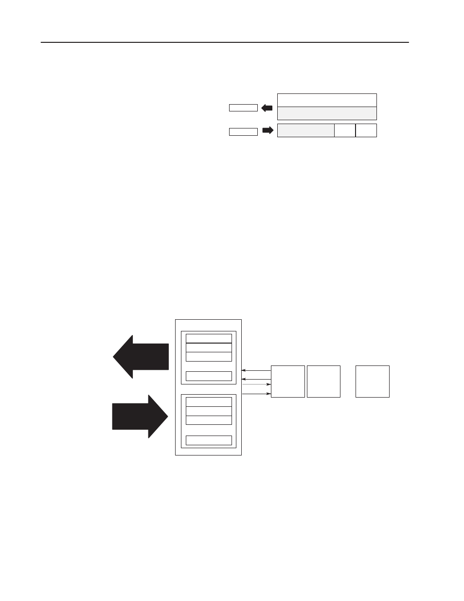
The first word of output data received by the adapter is the Adapter
Status Word. Output data is received by the adapter in the order of
the installed I/O modules. The Output data for Slot 1 is received
first, followed by the Output data for Slot 2, and so on up to slot 8.
All bits in the output status word are reserved
The first word of input data sent by the adapter is the Adapter Status
Word. This is followed by the input data from each slot, in the order
of the installed I/O modules. The Input data from Slot 1 is first after
the status word, followed by Input data from Slot 2, and so on up to
slot 8.
Adapter Status
Slot 1 Input Data
Slot 2 Input Data
Slot 8 Input Data
Slot 1 Output Data
Slot 2 Output Data
Slot 8 Output Data
Read Data
Write Data
Network READ
Network WRITE
PROFIBUS Adapter
Slot 1
I/O Module
Read
Write
Slot 2
I/O Module
Slot 8
I/O Module
...
...
...
...
...
Adapter Status
Polled I/O Structure