Setting the input filter – Rockwell Automation 1794-APB/B FLEX I/O PROFIBUS Adapter Module User Manual User Manual
Page 59
2–39
How Communication Takes Place and I/O Image Table Mapping
Publication 1794ĆUM057B-EN-P - November 2001
Size
00
01
02
03
04
05
06
07
08
09
10
11
12
13
14
15
Dec. Bit
Read/Write Words
00
01
02
03
04
05
06
07
10
11
12
13
14
15
16
17
Octal Bit
Word 8
Not used
Word 8
Where:
PU = Power up unconfigured state
FP = Field power off
CF = In configuration mode
BD = Calibration bad
DN = Calibration accepted
U = Under range for specified channel
V = Overrange for specified channel
EN = Enable outputs; 0 = output follows S1/S0, 1 = output enabled
IC = Initiate configuration bit
TR= Transparent bit
IT = Interrupt toggle bit
RV = Revert to defaults bit
QK = Quick calibration
CK = Calibration clock
GO = Gain offset select
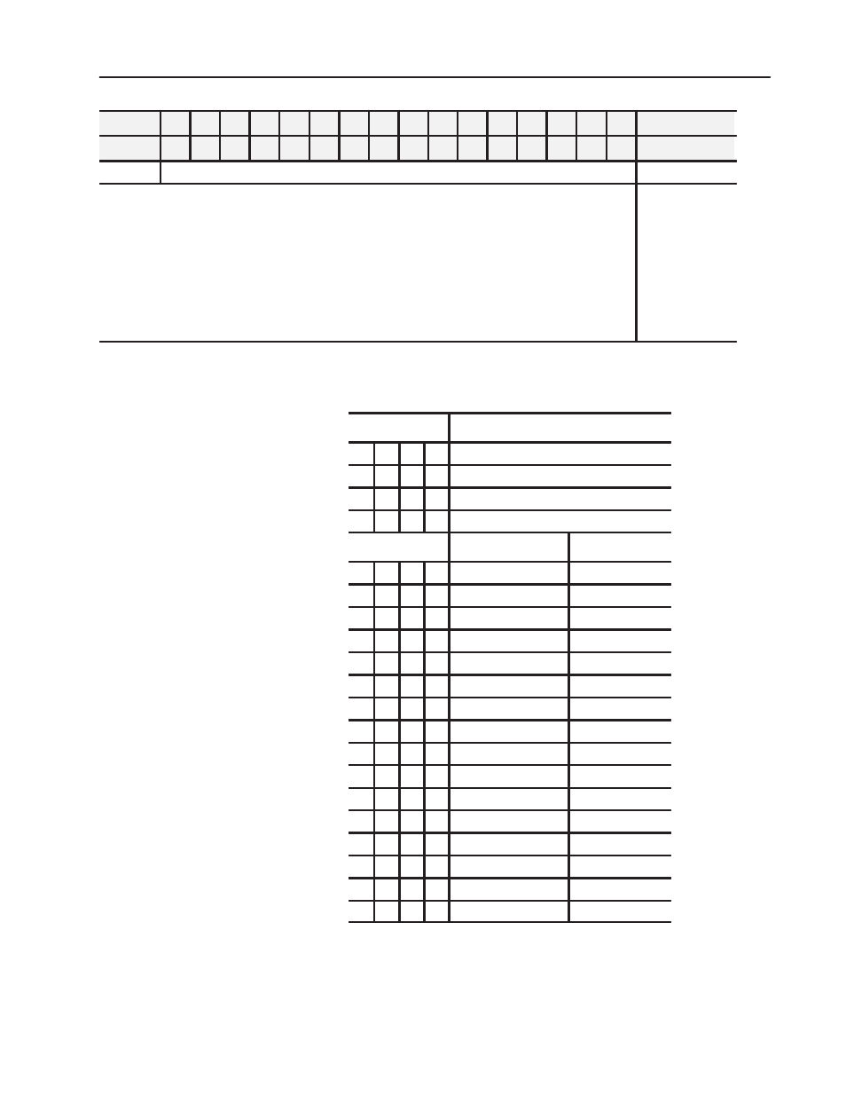
Setting the Input Filter
Bits
Channel
03 02 01 00 Input 0
07 06 05 04 Input 1
11 10 09 08 Input 2
15 14 13 12 Input 3
A/D Conversion Rate
Low Pass Filter
0
0
0
0 1200Hz
No low pass
0
0
0
1 1200Hz
100ms low pass
0
0
1
0 1200Hz
500ms low pass
0
0
1
1 1200Hz
1000ms low pass
0
1
0
0 600Hz
No low pass
0
1
0
1 600Hz
100ms low pass
0
1
1
0 600Hz
500ms low pass
0
1
1
1 600Hz
1000ms low pass
1
0
0
0 300Hz
No low pass
1
0
0
1 300Hz
100ms low pass
1
0
1
0 300Hz
500ms low pass
1
0
1
1 300Hz
1000ms low pass
1
1
0
0 150Hz
No low pass
1
1
0
1 150Hz
100ms low pass
1
1
1
0 150Hz
500ms low pass
1
1
1
1 150Hz
1000ms low pass
- 20P PowerFlex DC Drive - Frame D Bimetal Thermostat (10 pages)
- 1336S_F_T_E_R F Frame Snubber Resistor Repl. (6 pages)
- 22-COMM PowerFlex 4-Class DSI (Drive Serial Interface) Network Communication Adapter (4 pages)
- 8-545 Plug In Solid State Relay (2 pages)
- 20-HIM-B1 PowerFlex 7-Class HIM Bezel (DPI) (4 pages)
- 100 Contactors with DC Coil (1 page)
- 100 Contactors with DC Coil (2 pages)
- 20P PowerFlex DC Drive - Frame D Switching Power Supply Circuit Board (6 pages)
- 140G-MTFx_MTHx_MTIx_MTKx Trip Unit Installation-140G-M (6 pages)
- 45BRD Analog Laser Sensor (4 pages)
- 20D Multi-Device Interface Option Board for PowerFlex 700S Drives (20 pages)
- 56RF RFID 18 mm Cylindrical Transceiver (2 pages)
- 42KC Miniature Rectangular: 5V DC Version (2 pages)
- 20P PowerFlex DC Drive - Frame A Switching Power Supply Circuit Board (16 pages)
- 21P-MISC-A-TP-2 Transition Tube Kit #C19-6/7 For PowerFlex 755 w/OEM Liquid Cooling Fr 6/7 Drive (2 pages)
- 42BT Background Suppression Sensor (3 pages)
- 42CB High Speed 18mm Cylindrical (4 pages)
- 140EX-JE2_JE3 Molded Case Circuit Breaker (4 pages)
- 140G-K-EAM1A Early Make Aux Contact for Rotary Handle Oper Mech-140G-K (1 page)
- 140G-K-EAM1A Early Make Aux Contact for Rotary Handle Oper Mech-140G-K (3 pages)
- 20-HIM-A6 PowerFlex (Human Interface Module) (74 pages)
- 42CF General Purpose 12mm Cylindrical (4 pages)
- 20D PowerFlex 700S Phase II Drive Frames 1...6 (80 pages)
- 140EX-HE1_HE2 Molded Case Circuit Breaker (6 pages)
- 140EX-HE1_HE2 Molded Case Circuit Breaker (4 pages)
- 20B PowerFlex 700 Custom Firmware - Pump Off (12 pages)
- 20-WIM-N4S DPI Wireless Interface Module (92 pages)
- 140U H-Frame Circuit Breaker Fixed and Adjustable Thermal Trip (7 pages)
- 140U H-Frame Circuit Breaker Fixed and Adjustable Thermal Trip (2 pages)
- 60-2619, 42JS Swivel/Tilt Mounting Bracket (1 page)
- 22A PowerFlex 4/40/400 Flange Mount (4 pages)
- 45MLA Controller Installation Instructions (16 pages)
- 20P PowerFlex DC Drive - Cooling Fan for Frame A Drives Above 73A at 230V 460V AC (6 pages)
- 42JS Series 7000 to 42JS VisiSight Replacement Kit (2 pages)
- 22A PowerFlex 4-Class HIM Bezel (DSI) (4 pages)
- 42CS Stainless Steel Photoelectric Sensors (4 pages)
- 20L-LL PowerFlex 700L Liquid-to-Liquid Heat Exchanger (40 pages)
- 20P PowerFlex DC Drive - Frame B SCR Modules (20 pages)
- 22B PowerFlex 40 Quick Start FRN 5.xx - 6.xx (161 pages)
- 22B PowerFlex 40 Quick Start FRN 5.xx - 6.xx (22 pages)
- 22F PowerFlex 4M Input RFI Filters (2 pages)
- 45LFM Capacitive Label Sensor (4 pages)
- 140G-Rx Installation Instruction-140G-R (29 pages)
- 140G-Rx Installation Instruction-140G-R (2 pages)
- 22C PowerFlex 400 AC Drive Quick Start - FRN 1-4.xx (28 pages)