Rockwell Automation 1794-APB/B FLEX I/O PROFIBUS Adapter Module User Manual User Manual
Page 81
2–61
How Communication Takes Place and I/O Image Table Mapping
Publication 1794ĆUM057B-EN-P - November 2001
00
01
02
03
04
05
06
07
10
11
12
13
14
15
16
17
(Octal Bit
⇒
)
00
01
02
03
04
05
06
07
08
09
10
11
12
13
14
15
Dec. Bit
⇒
Word
⇓
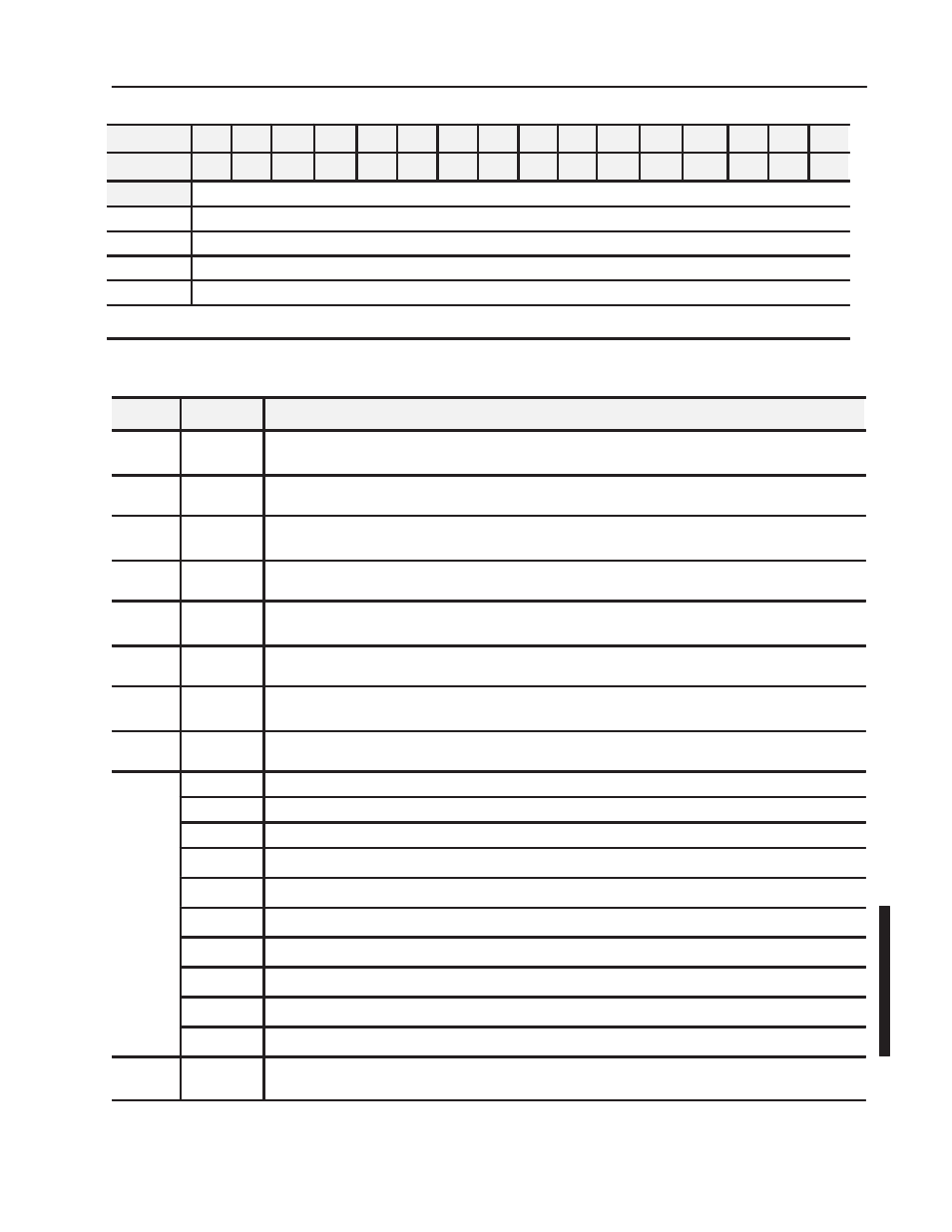
Write
1
Control Word 0 - se le cts the me asurefunction
2
Control Word 1 - sets the clock frequency and period multiple
3
Control Word 2 - sets the start of a new measurement
4-5
Reserved
Where: M = positive edge measurement ready for the respective channel.
RD = Reset Done for respective channel.
Bit/Word Definitions
for the Pulse Counter Module
Word
Bit
Definition
Read
Word 1
Bits 00-15
(00-17)
Store Counter 00 - 16-bit period measurement or low word of 32Ćbit period measurement for channel 0.
Read
Word 2
Bits 00-15
(00-17)
Counter 01 - pulse counter or high word of 32Ćbit period measurement for channel 0
Read
Word 3
Bits 00-15
(00-17)
Counter 10 - 16-bit period measurement or low word of 32Ćbit period measurement for channel 1.
Read
Word 4
Bits 00-15
(00-17)
Counter 11 - pulse counter or high word of 32Ćbit period measurement for channel 1
Read
Word 5
Bits 00-15
(00-17)
Counter 20 - 16-bit period measurement or low word of 32Ćbit period measurement for channel 2.
Read
Word 6
Bits 00-15
(00-17)
Counter 21 - pulse counter or high word of 32Ćbit period measurement for channel 2
Read
Word 7
Bits 00-15
(00-17)
Counter 30 - 16-bit period measurement or low word of 32Ćbit period measurement for channel 3.
Read
Word 8
Bits 00-15
(00-17)
Counter 31 - pulse counter or high word of 32Ćbit period measurement for channel 3
Read
Word 9
Readback ofControl Word 2
Word 9
Bit 00
Positive edge - Channel 0 - measurement ready
Bit 01
Positive edge - Channel 1 - measurement ready
Bit 02
Positive edge - Channel 2 - measurement ready
Bit 03
Positive edge - Channel 3 - measurement ready
Bit 04
Reset Done, Channel 0 - a positive edge on this bit indicates counter 01 reset done
Bit 05
Reset Done, Channel 1 - a positive edge on this bit indicates counter 11 reset done
Bit 06
Reset Done, Channel 2 - a positive edge on this bit indicates counter 21 reset done
Bit 07
Reset Done, Channel 3 - a positive edge on this bit indicates counter 31 reset done
Bit 08-15
Reserved for factory use
Read
Word 10
Bits 00-15
(00-17)
Software revision - version codeof softwareinstalled