Rockwell Automation 1794-APB/B FLEX I/O PROFIBUS Adapter Module User Manual User Manual
Page 53
2–33
How Communication Takes Place and I/O Image Table Mapping
Publication 1794ĆUM057B-EN-P - November 2001
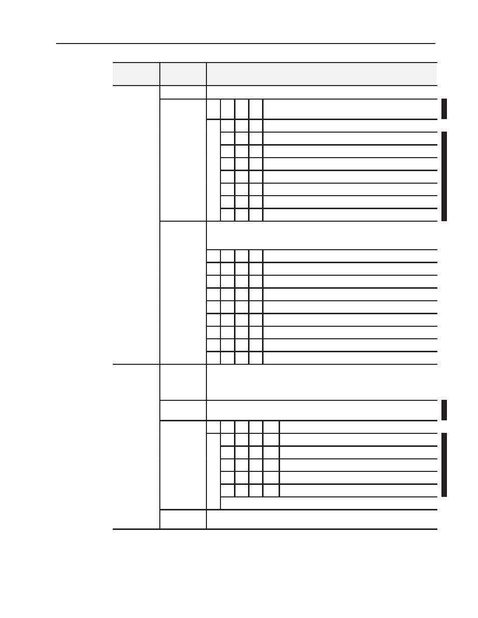
Description
Dec. Bits
(Octal Bits)
Word
Write Word 1
00-02
Input Filter Cutoff bits
Bit 02 01 00 Filter Time Constants - actual filtering depends on the module's
mode of operation
0
0
0 Hardware filtering only (default filtering)
0
0
1 25ms
0
1
0 100ms
0
1
1 250ms
1
0
0 500ms
1
0
1 1s
1
1
0 2s
1
1
1 5s
Bits 03-05
Reference Junction - used when input type is set to thermocouple and sensor mode
is set to internal compensation. Sets a fixed reference junction to compensate all
thermocouple channels.
Bit 05 04 03 Reference Junction
0
0
0 0
o
C
0
0
1 20
o
C
0
1
0 25
o
C
0
1
1 30
o
C
1
0
0 40
o
C
1
0
1 50
o
C
1
1
0 60
o
C
1
1
1 70
o
C
Write Word 1
Contimued
Bits 06-07
Fault Mode bits - when a bit is set (1), fault mode is enabled for that channel. Bit 06
corresponds to channels 0-3; bit 07 corresponds to channels 4-7.
0 = disabled
1 = enable wireĆoff detection
Bits 08-11
(10-13)
Data format - module defaults to -4000 to 10000 in millivolt mode, and 0 to 5000 in
ohms mode with implied decimal points (i.e. -40.00, 0.0
Ω
)
Bit 11 10 09 08
Data type for channels 0-7
0
0
0 0
o
C (implied decimal point XXXX.X)
0
0
0 1
o
F (implied decimal point XXXX.X)
0
0
1 0
o
K (implied decimal point XXXX.X)
0
0
1 1
-32767 to +32767
0
1
0 0
0 to 65535
0101 through 1111 not used
Bits 12-15
(14-17)
Not used