Chapter – Rockwell Automation 1794-APB/B FLEX I/O PROFIBUS Adapter Module User Manual User Manual
Page 21
Chapter
2
Publication 1794ĆUM057B-EN-P - November 2001
How Communication Takes
Place and I/O Image Table
Mapping
In this chapter, you will learn about:
•
communication over the FLEX I/O backplane (between the
PROFIBUS adapter and the I/O modules)
•
how data is mapped into the I/O image table
One 1794-APB PROFIBUS adapter can interface with up to eight
terminal base units with installed FLEX I/O modules, forming a
FLEX I/O system of up to eight slots. The adapter communicates to
other network system components over the PROFIBUS network.
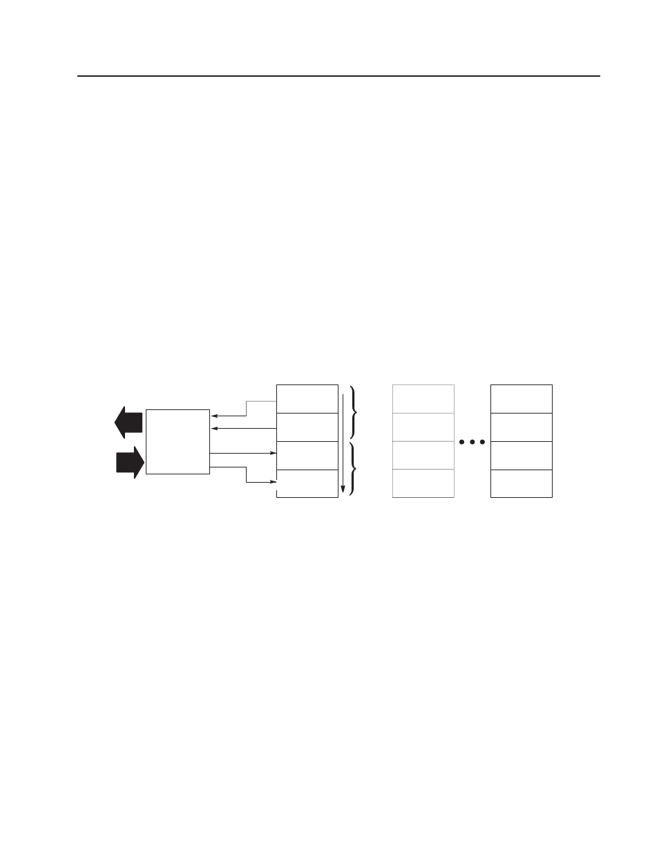
The adapter communicates with its I/O modules over the backplane.
Inputs
Status
Outputs
Configuration
Slot 1
I/O Module
Read
Words
Write
Words
0
15
Read
Write
PROFIBUS
Adapter
Inputs
Status
Outputs
Configuration
Slot 2
I/O Module
Inputs
Status
Outputs
Configuration
Slot 8
I/O Module
Network
The I/O map for a module is divided into read words and write
words. Read words consist of input and status words, and write
words consist of output and configuration words. The number of
read words or write words can be 0 or more. The length of each I/O
module’s read words and write words vary in size depending on
module complexity. Each I/O module will support at least 1 input
word or 1 output word. Status and configuration are optional,
depending on the module.
What this Chapter Contains
Communication Over
the I/O Backplane